


Power Wagon Rebuild (Update: 11/5/08)


Thread Starter
1.0 BAR
Joined: Feb 2003
Posts: 461
From: Wisconsin

more for wow factor than anything else. I could get to my power level with one big turbo, but plumbing two was easier. A single Eaton m90 would have been a restriction with the CID of the engine, and an Eaton m112 are hard to find.

0.5 BAR
Joined: Mar 2009
Posts: 76
Im all about efficient but i like this over the top style. Looks amazing and i got to say you got mad skills. not only are you doing a twin turbo bi super charger, but hell your intake manifolds were molded from wood you carved from wood you did yourself. mad props bro!!

Thread Starter
1.0 BAR
Joined: Feb 2003
Posts: 461
From: Wisconsin
here is the latest and greatest:
Scored some parts for the rig. Got TWO Ramsey RE12000 Winches, brand new for $900... a friggin STEAL! They pull 6 TONS each!
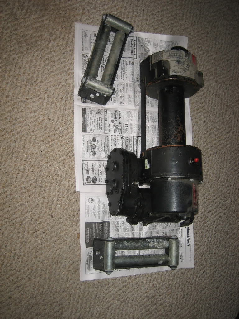
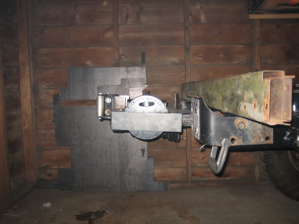
The plan is to replace the front LU4 with one, and then make a trailer hitch mount to mount the second on the back. I also plan on making some hitch mounts that will bolt to the sides of the frame, just in front of the rear tires for this:
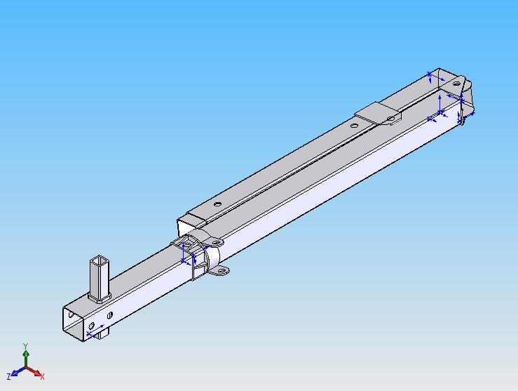
It is a folding crane. The small tube sticking up at the bottom will be a receiver where the winch will bolt on, then stick through the crane with a pin, then pin into the receiver on the truck, either in the back, or on the sides. This way, when I go junkyard hunting, I can pull stuff up to the side of the truck, and pick it up with the crane.
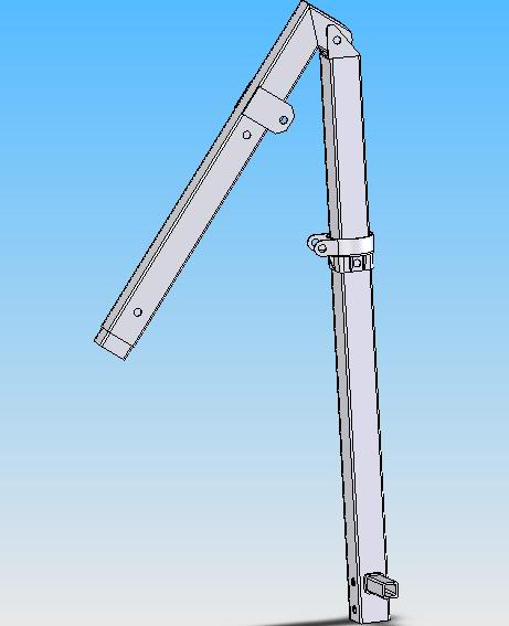
A hydraulic foot will be pinned into the bottom hole, and extend down to hold the weight of the crane off the truck frame. The boom will have an extension joint, and the sliding slip ring will adjust the mounting point for the cylinder that will raise and lower the boom, and I'll mount a small 2K lb winch on top near the swing joint to lift the load. The collar is designed to swivel, so it will swing round 360*. Best part is that it will fold down small enough to fit into the toolbox pocket in the bed!
Arm extended out:
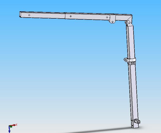
arm extension folded in:
Scored some parts for the rig. Got TWO Ramsey RE12000 Winches, brand new for $900... a friggin STEAL! They pull 6 TONS each!
The plan is to replace the front LU4 with one, and then make a trailer hitch mount to mount the second on the back. I also plan on making some hitch mounts that will bolt to the sides of the frame, just in front of the rear tires for this:
It is a folding crane. The small tube sticking up at the bottom will be a receiver where the winch will bolt on, then stick through the crane with a pin, then pin into the receiver on the truck, either in the back, or on the sides. This way, when I go junkyard hunting, I can pull stuff up to the side of the truck, and pick it up with the crane.
A hydraulic foot will be pinned into the bottom hole, and extend down to hold the weight of the crane off the truck frame. The boom will have an extension joint, and the sliding slip ring will adjust the mounting point for the cylinder that will raise and lower the boom, and I'll mount a small 2K lb winch on top near the swing joint to lift the load. The collar is designed to swivel, so it will swing round 360*. Best part is that it will fold down small enough to fit into the toolbox pocket in the bed!
Arm extended out:
arm extension folded in:
Thread Starter
1.0 BAR
Joined: Feb 2003
Posts: 461
From: Wisconsin
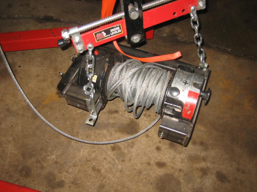
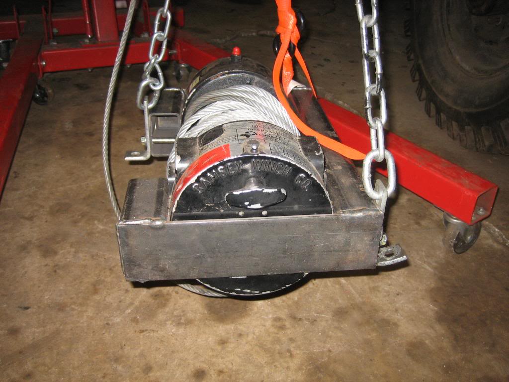
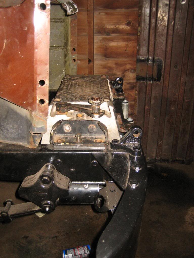
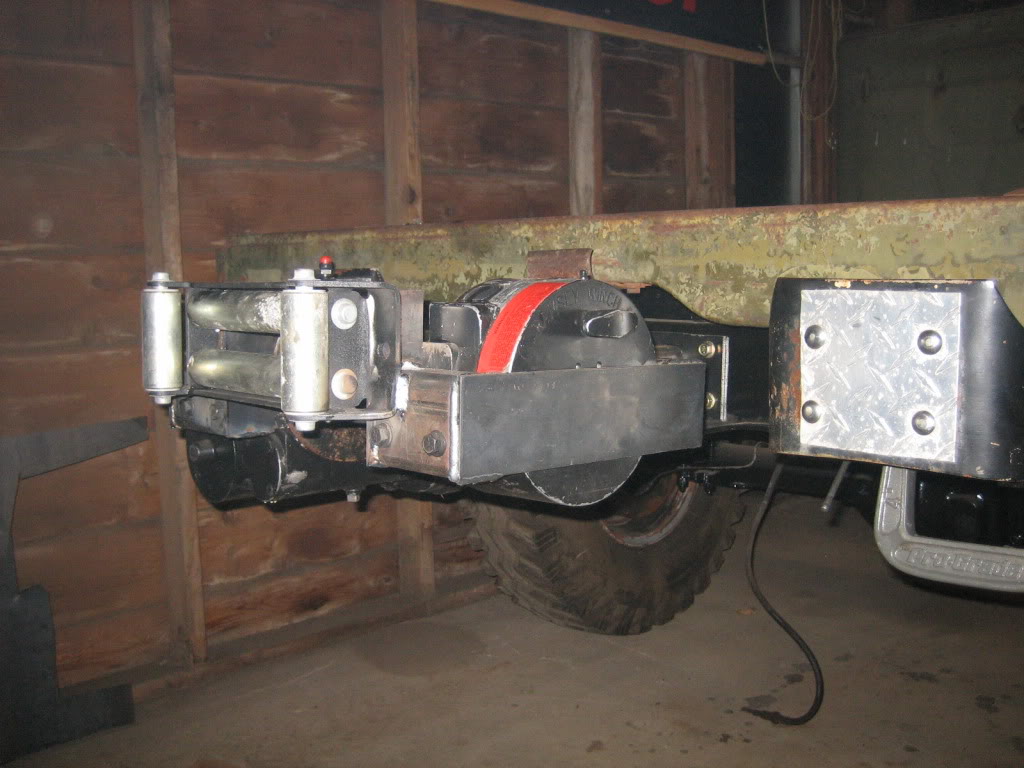
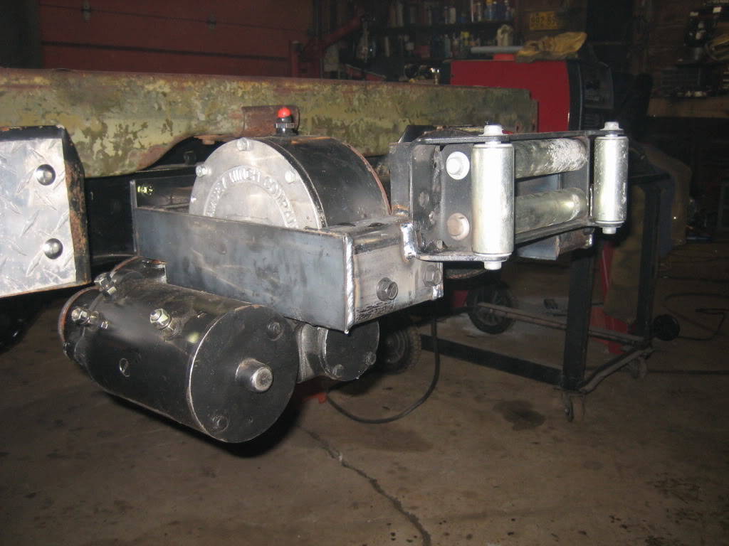
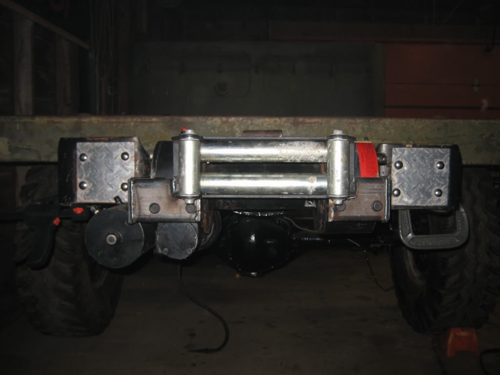
finished mounting the front winch, on to the rear one. Here is the front however:
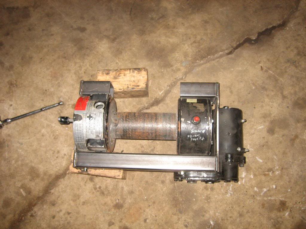
the carrier for the winch:
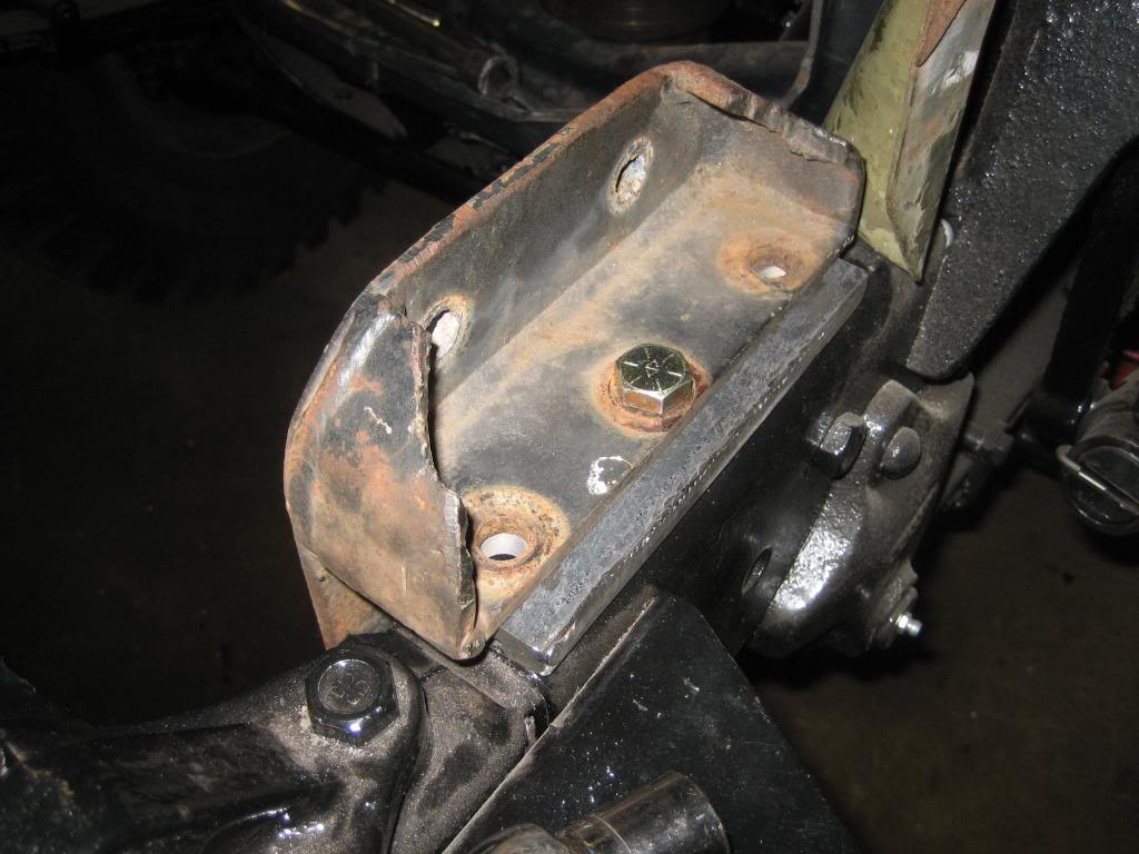
C channel brackets on the frame. This is how Dodge should have done it to start. It captures all 5 of the 1/2" bolts:


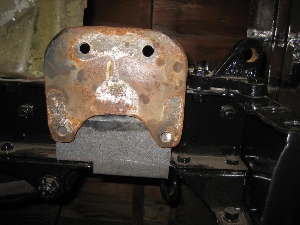
Old brackets over the new ones, you'll see why in a bit:
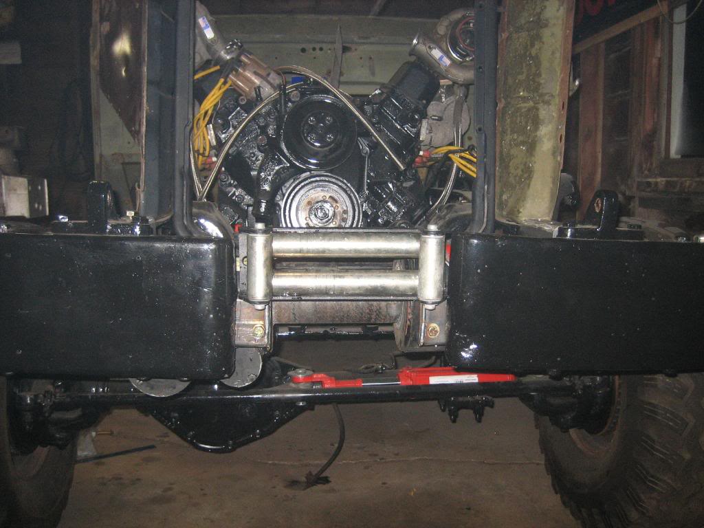
Roller fairlead is mounted to the carrier. I put it up high enough that it should feed straight out on the 4th and 3rd wraps, as I figure there will be very few times I spool out enough cable to get down to layers 1 and 2:
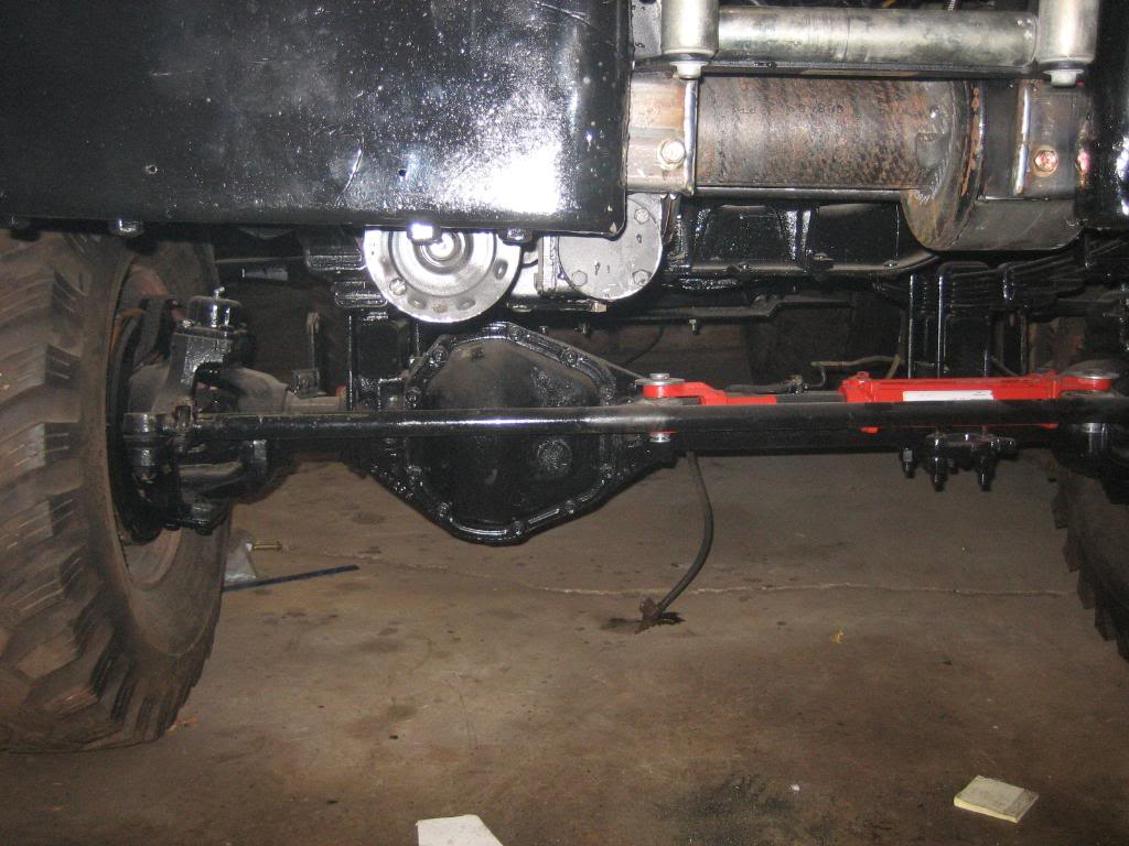
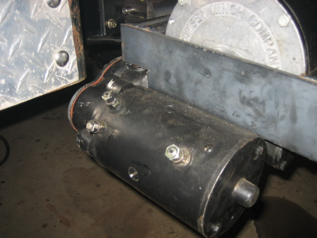
only downside to my mounting job... motor hangs down a bit. I might come back later and make a little skidplate for it:
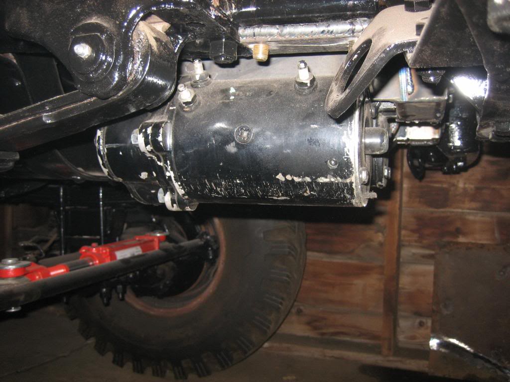
still plenty of room to get the wire lugs on the motor studs. I plan on mounting the solenoids up on the firewall:
Mounted in, all 1/4" plate or tube:

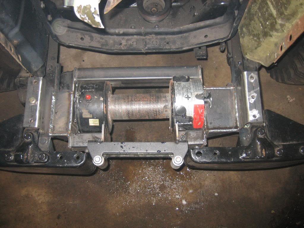
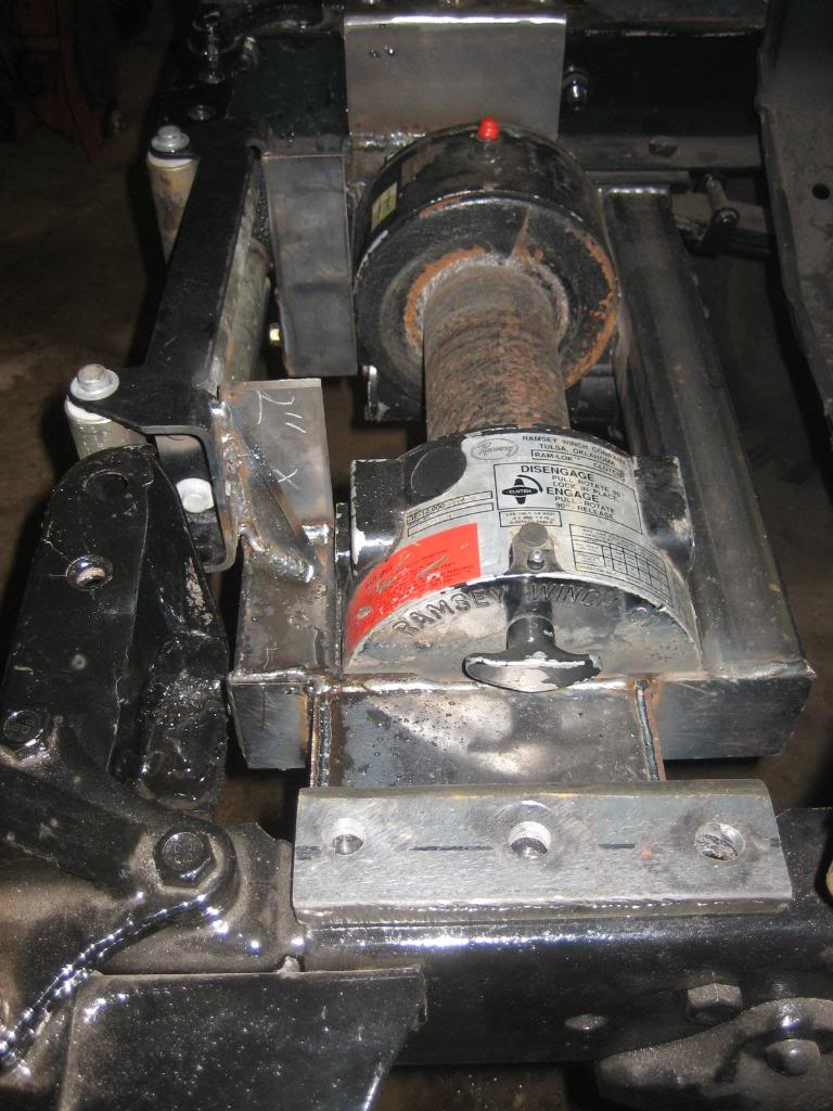
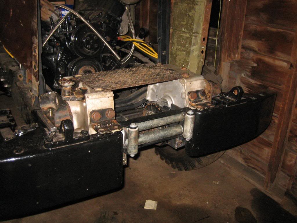
and, here is the reason for the original brackets. I love the look of the original winch, but, since mine got trashed, I did the next best thing and made the original cases into covers, so the new one looks like the original. I bet 98% of the people who will ever look at it wont' even be able to tell it's not original. They are not finalized in their locations yet, just kinda sitting on top for now:
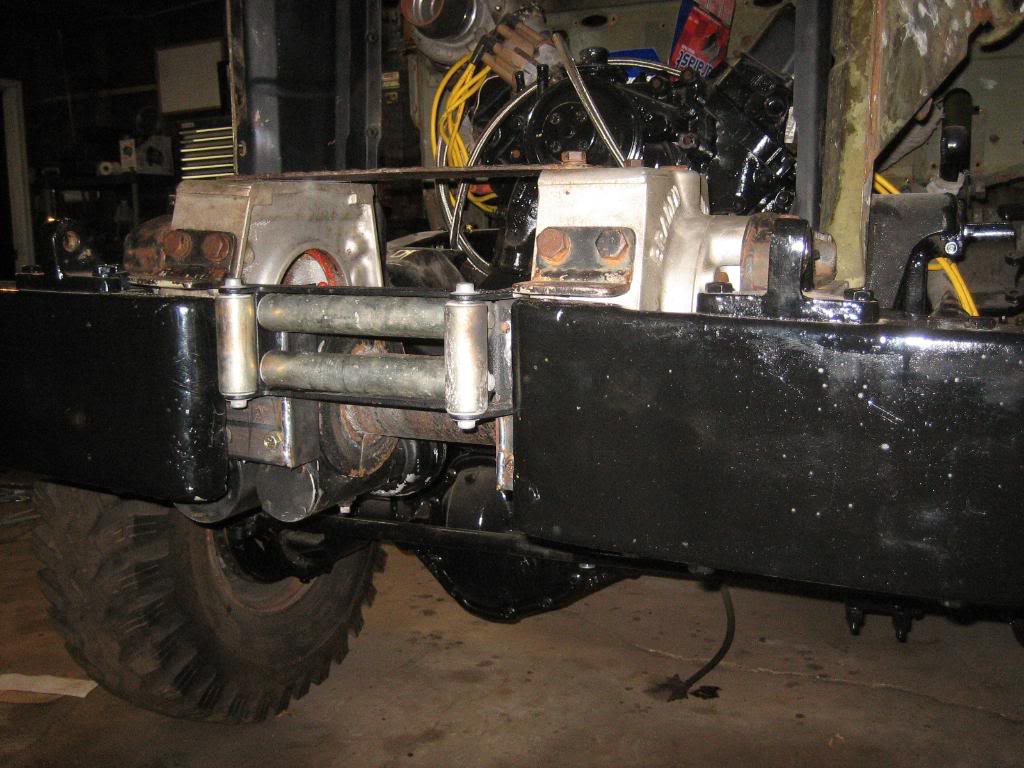
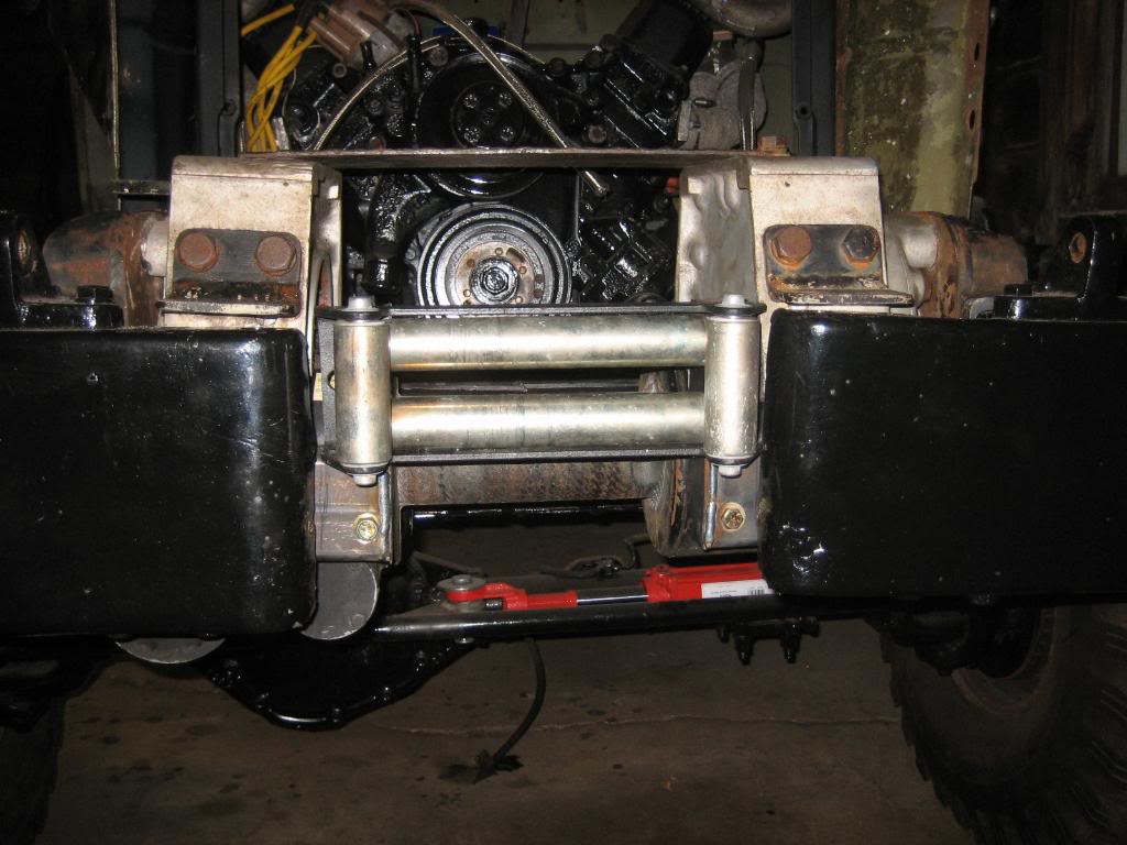
I am going to make covers that bolt to the insides of the cases to hide the original drum shaft holes:
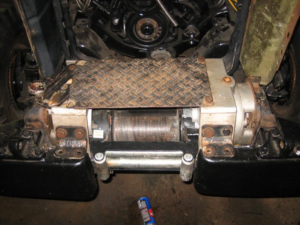
the carrier for the winch:
C channel brackets on the frame. This is how Dodge should have done it to start. It captures all 5 of the 1/2" bolts:
Old brackets over the new ones, you'll see why in a bit:
Roller fairlead is mounted to the carrier. I put it up high enough that it should feed straight out on the 4th and 3rd wraps, as I figure there will be very few times I spool out enough cable to get down to layers 1 and 2:
only downside to my mounting job... motor hangs down a bit. I might come back later and make a little skidplate for it:
still plenty of room to get the wire lugs on the motor studs. I plan on mounting the solenoids up on the firewall:
Mounted in, all 1/4" plate or tube:
and, here is the reason for the original brackets. I love the look of the original winch, but, since mine got trashed, I did the next best thing and made the original cases into covers, so the new one looks like the original. I bet 98% of the people who will ever look at it wont' even be able to tell it's not original. They are not finalized in their locations yet, just kinda sitting on top for now:
I am going to make covers that bolt to the insides of the cases to hide the original drum shaft holes:
Thread Starter
1.0 BAR
Joined: Feb 2003
Posts: 461
From: Wisconsin
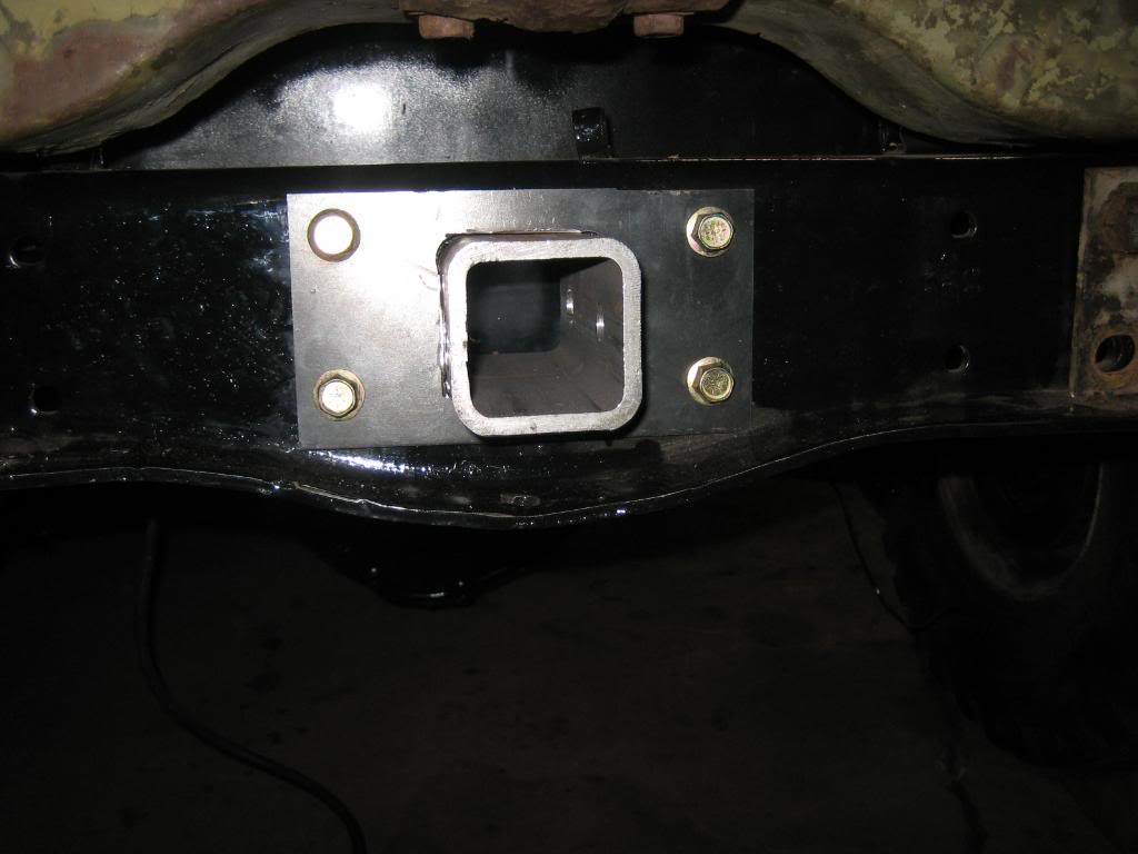
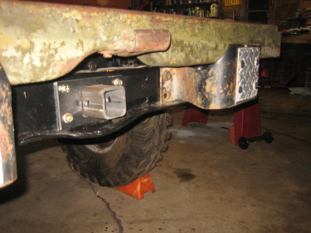
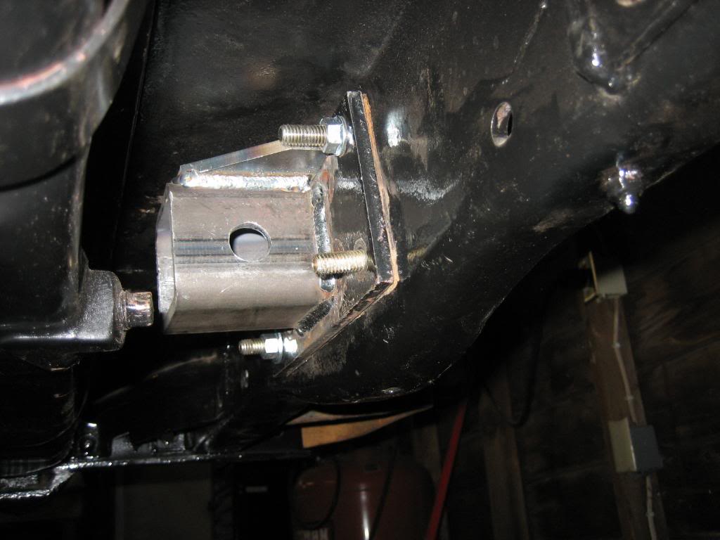
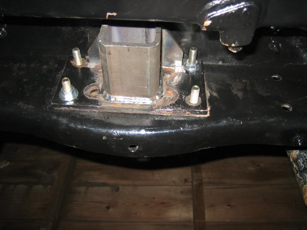
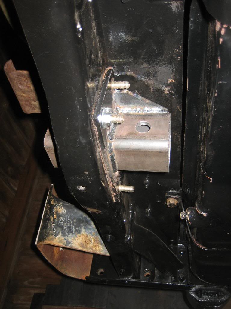
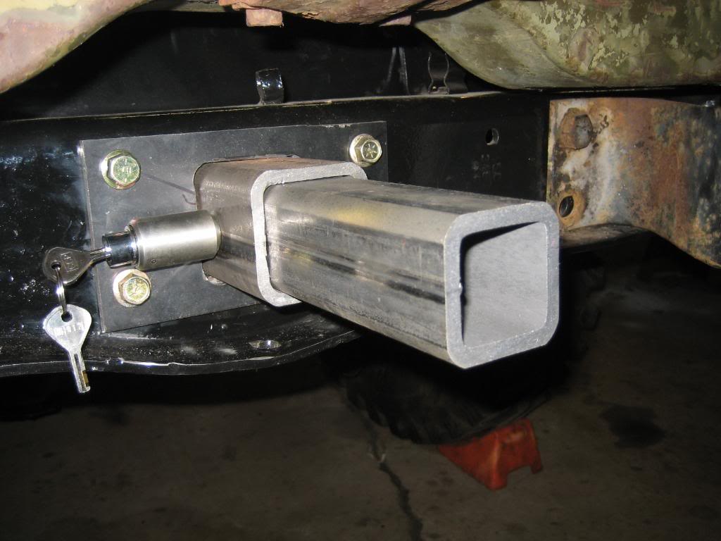
Finished the rear conversion to a standard 2" tube type receiver hitch. this will let me put a regular ball on, as well as the factory pintle, and the rear winch. I drilled a 5/8" receiver pin hole, for a locking, O ringed stainless steel pin, as well as a larger, 3/4" hole behind the frame for a load bearing 3/4" bolt when the winch is in. I welded a top plate above the tube, to the plate behind the frame, for some lateral support in sideways pulls
Question for you guys:
In the front, would you weld the cover plate to the hitch, or leave it bolted as-is? I dont really like the look of the gap around the tube, and, I don't see why I would ever have to remove the hitch, but, if I welded the plate to the tube, removing it could really, really suck...
Stock:
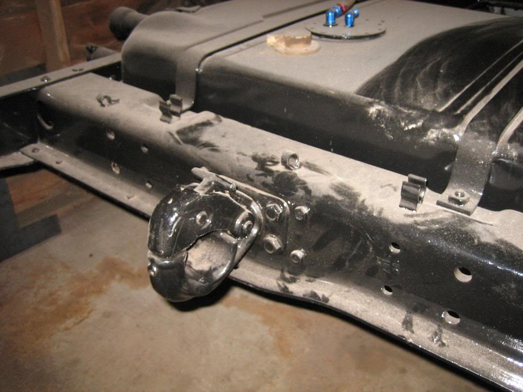
After:
SS locking pin, to deter the theves...

Bolt for load bearing when the winch is in. Camera angle makes it look crooked but it is straight:

Question for you guys:
In the front, would you weld the cover plate to the hitch, or leave it bolted as-is? I dont really like the look of the gap around the tube, and, I don't see why I would ever have to remove the hitch, but, if I welded the plate to the tube, removing it could really, really suck...
Stock:
After:
SS locking pin, to deter the theves...
Bolt for load bearing when the winch is in. Camera angle makes it look crooked but it is straight:

Thread Starter
1.0 BAR
Joined: Feb 2003
Posts: 461
From: Wisconsin
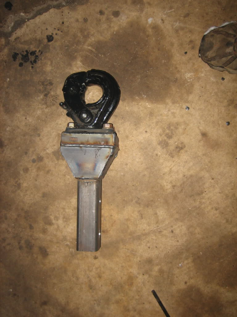
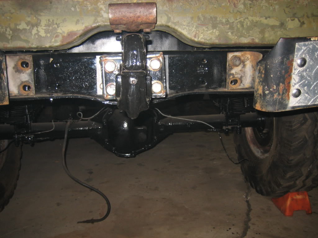
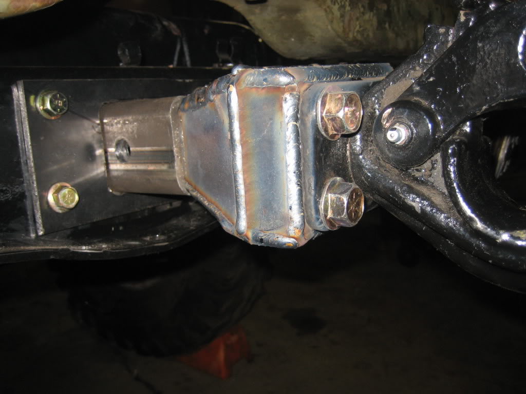
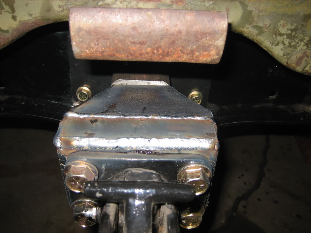
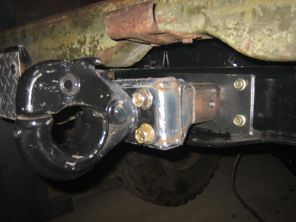
a bit more progress. Finished the pintle hitch conversion. Will work on the winch tonight. Sandwiched a plate between the two factory plates, then bolted it all together, then welded the body to the plate between the two. can still get to the grease zerk from underneath, and it still swivels.
Also worked out what to do for ignition. Read up on ignition KV as it relates to cylinder pressure. Under a bar of boost, I will have equivalent cylinder pressures to 245 or so PSI, not including the volume occupied by the fuel, but, also not taking into account leakdown and such, so, it's probably pretty close. at 245 PSI, you need 21KV to fire a plug with a .030 gap. Reason I looked into this is I have these very nice, very FREE coils:

Problem is, said coils only output 15KV, so, I am out of luck.
I'll instead be running GM LS2 coils:

these output 45-50KV, have a dwell time of only 5 mS, and output 150mJ of energy at the plug. Basically, they are 2-3 times more powerful than a normal distributed V8 coil, and could probably fire a spark plug under 15 PSI of boost with a .040 or possibly bigger gap!
Also worked out what to do for ignition. Read up on ignition KV as it relates to cylinder pressure. Under a bar of boost, I will have equivalent cylinder pressures to 245 or so PSI, not including the volume occupied by the fuel, but, also not taking into account leakdown and such, so, it's probably pretty close. at 245 PSI, you need 21KV to fire a plug with a .030 gap. Reason I looked into this is I have these very nice, very FREE coils:
Problem is, said coils only output 15KV, so, I am out of luck.
I'll instead be running GM LS2 coils:
these output 45-50KV, have a dwell time of only 5 mS, and output 150mJ of energy at the plug. Basically, they are 2-3 times more powerful than a normal distributed V8 coil, and could probably fire a spark plug under 15 PSI of boost with a .040 or possibly bigger gap!
Thread Starter
1.0 BAR
Joined: Feb 2003
Posts: 461
From: Wisconsin
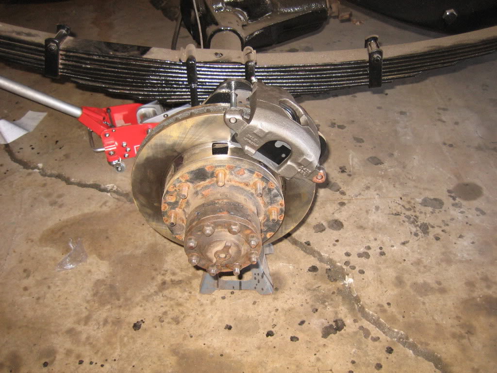
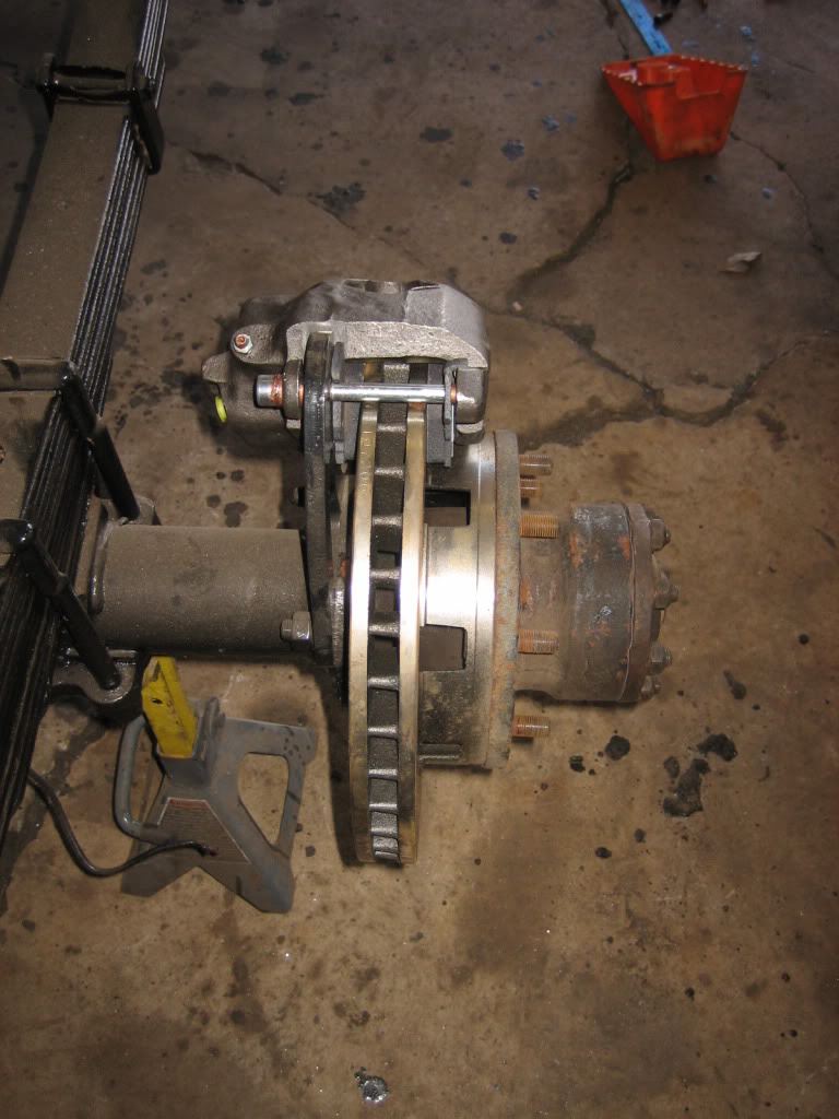
bit more work done. Got the calipers and pads for the rear axle, as well as the hub flange gaskets.
Then, I had an idea... :twisted:
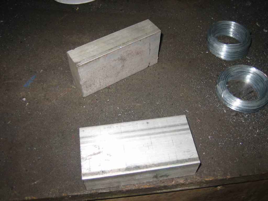
2' of 2"X2" 6061 billet:
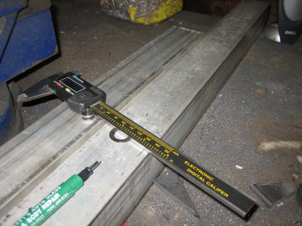
4" of said billet:
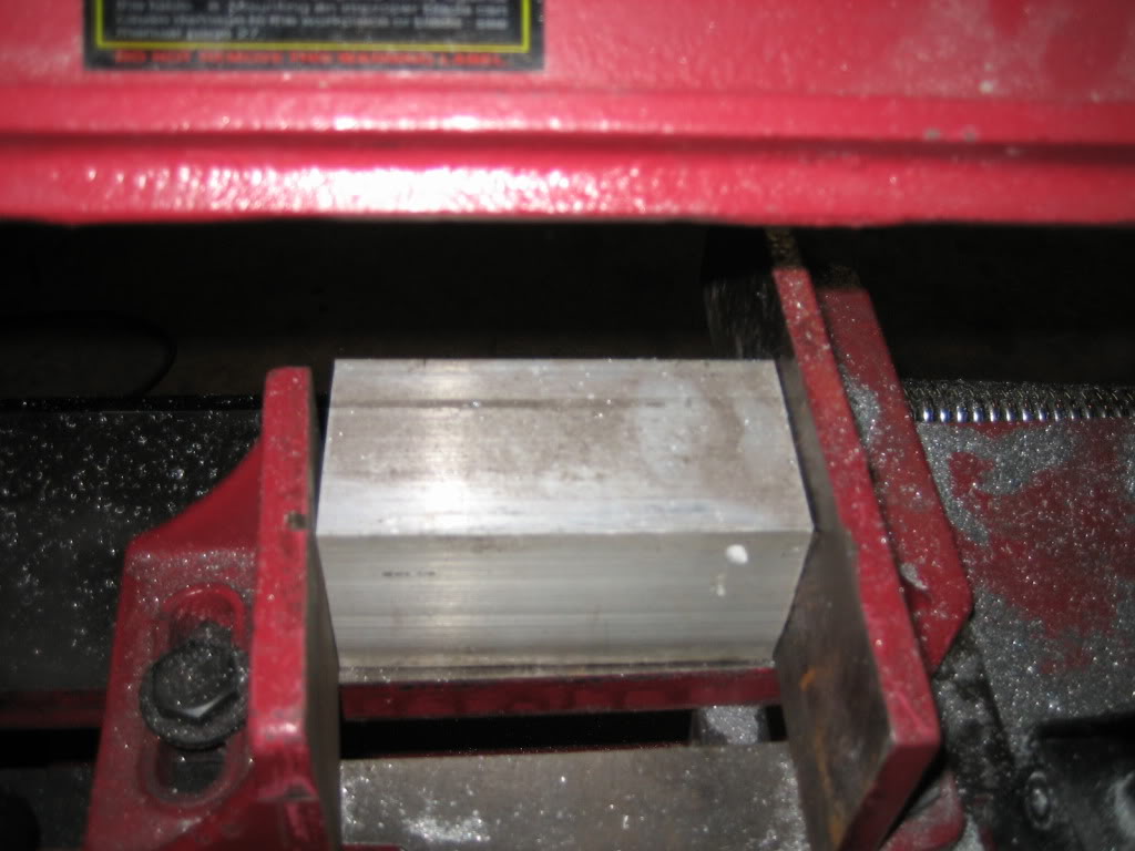
4" of billet cut in half:
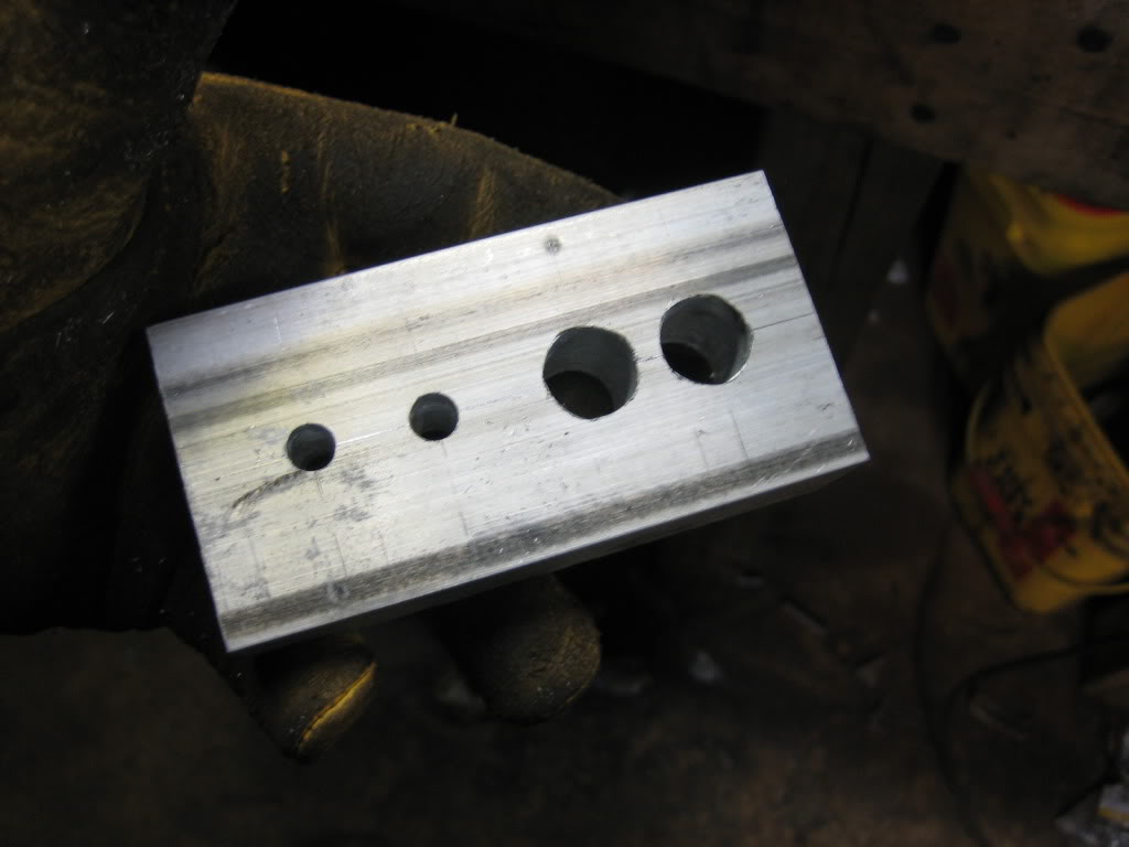
4" of billet drilled:
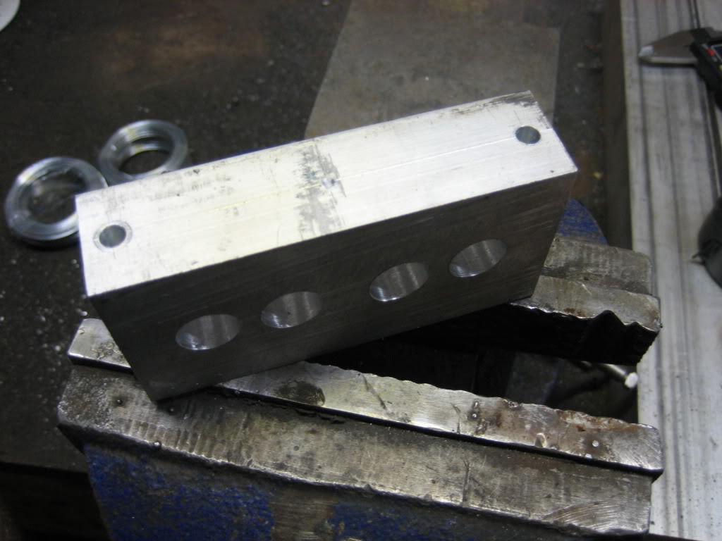
drilled again:
sawed again:
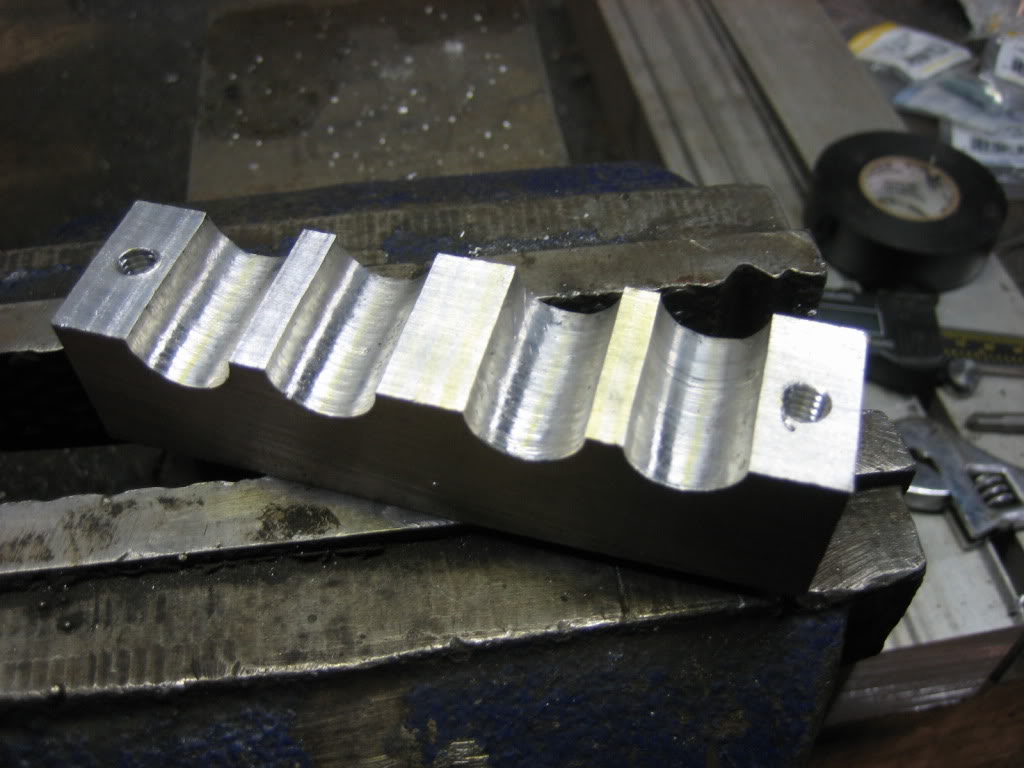
threaded:
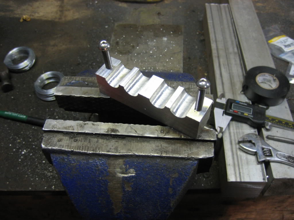
counterbored the other half:
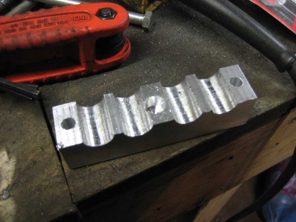
for this:
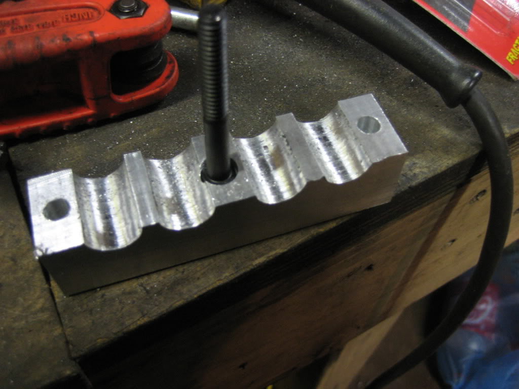
to do this:
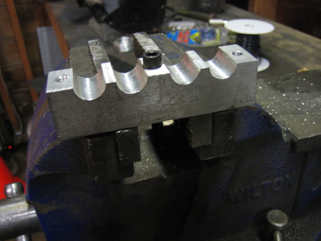
put it all back together:

and, the reason for the insanity:
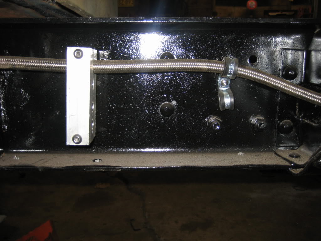
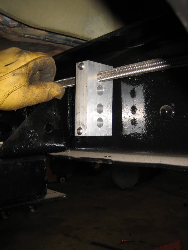
Much prettier than those ugly rubber lined stamped steel clamps. Plus, once I set up a mini "assembly line" I cranked out 4 of em in about an hour. I can make them for all different lines... brake lines, electrical lines, fuel lines, hydraulic lines, air lines, etc. Best part is that I can vary the height to add or remove holes of all different sizes for different sizes of lines. I drilled 4 holes in this set as I am going to have 4 6AN fuel lines, 2 feed, 2 return, heading up to the engine.
Then, I had an idea... :twisted:
2' of 2"X2" 6061 billet:
4" of said billet:
4" of billet cut in half:
4" of billet drilled:
drilled again:
sawed again:
threaded:
counterbored the other half:
for this:
to do this:
put it all back together:
and, the reason for the insanity:
Much prettier than those ugly rubber lined stamped steel clamps. Plus, once I set up a mini "assembly line" I cranked out 4 of em in about an hour. I can make them for all different lines... brake lines, electrical lines, fuel lines, hydraulic lines, air lines, etc. Best part is that I can vary the height to add or remove holes of all different sizes for different sizes of lines. I drilled 4 holes in this set as I am going to have 4 6AN fuel lines, 2 feed, 2 return, heading up to the engine.


