
Power Wagon Rebuild (Update: 11/5/08)


Thread Starter
1.0 BAR
Joined: Feb 2003
Posts: 461
From: Wisconsin
thanks guys.... more progress:
2 1/2 months later...
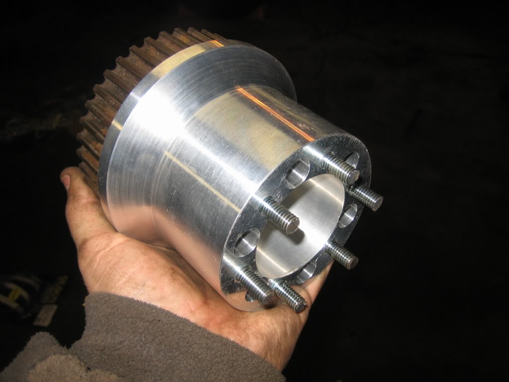
The Blower hub is DONE!!!
He made one small booboo... The 6 larger holes drilled to take mass out he didn't drill on the proper centerline, so they came really, really close to breaking out on the inside bore, but, it's OK down on the end that mates to the crank, so, I asked for a nice discount and took it as-is rather than making him make another one.
From this:
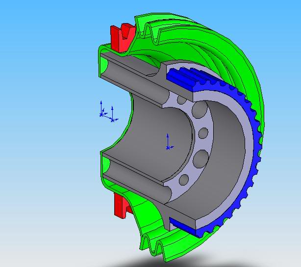
To this:
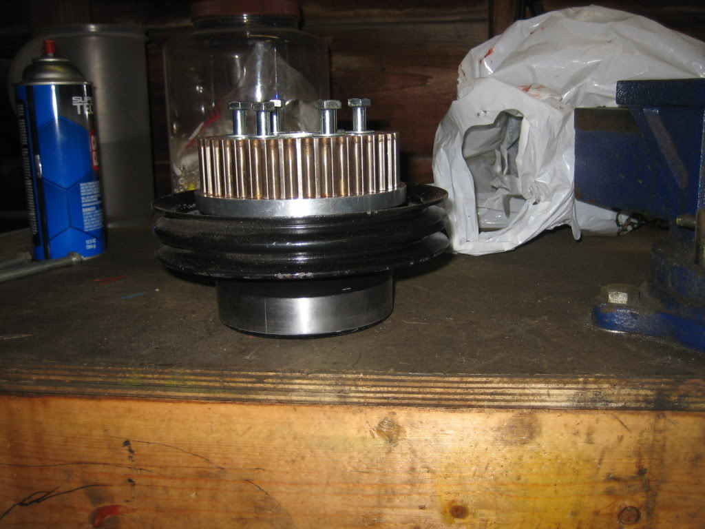
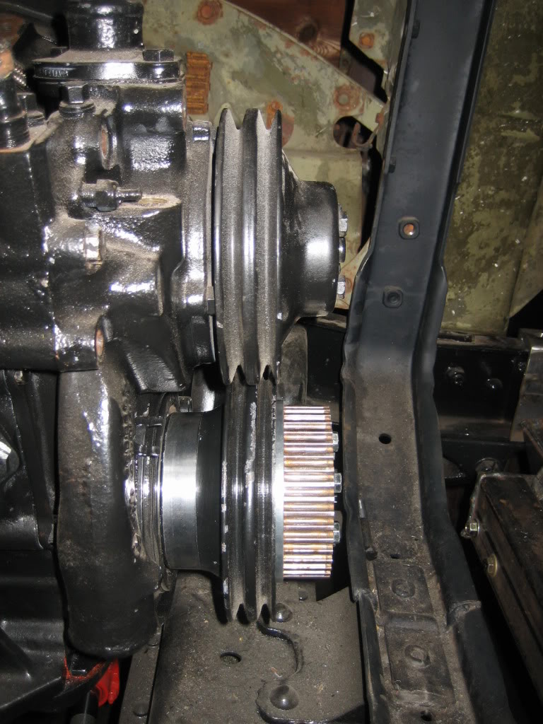
Crank position ring not pressed all the way down. Will do that once I figure out how I want to mount the position sensor:
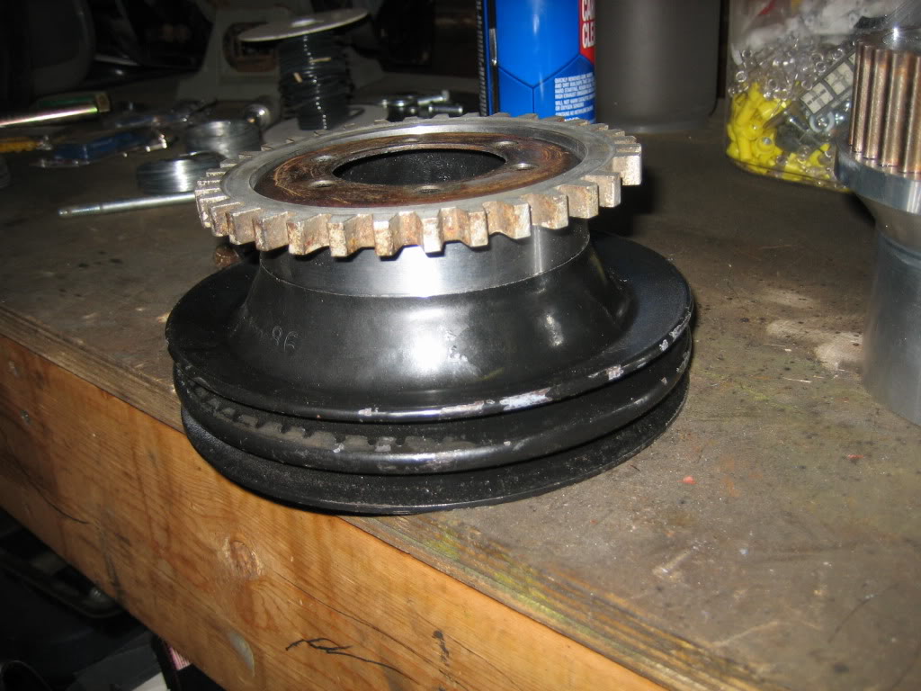
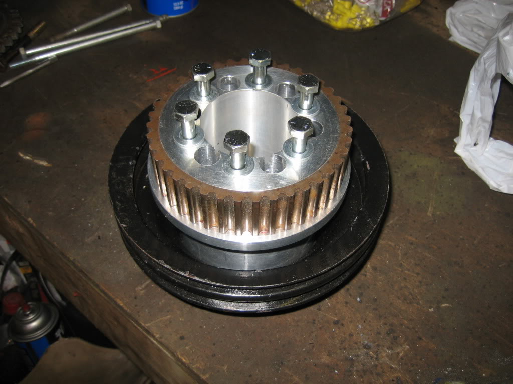
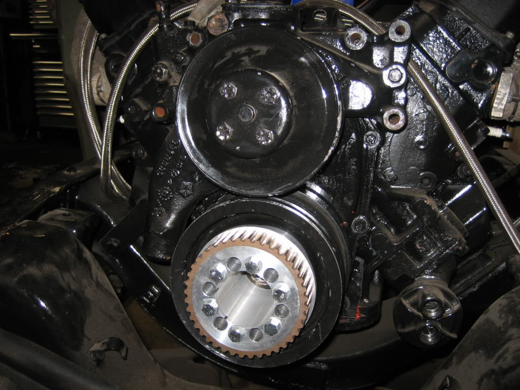
Beef baby, Beef:
mounted:
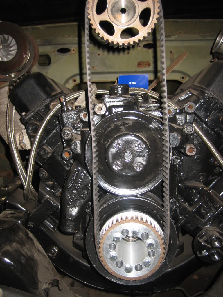
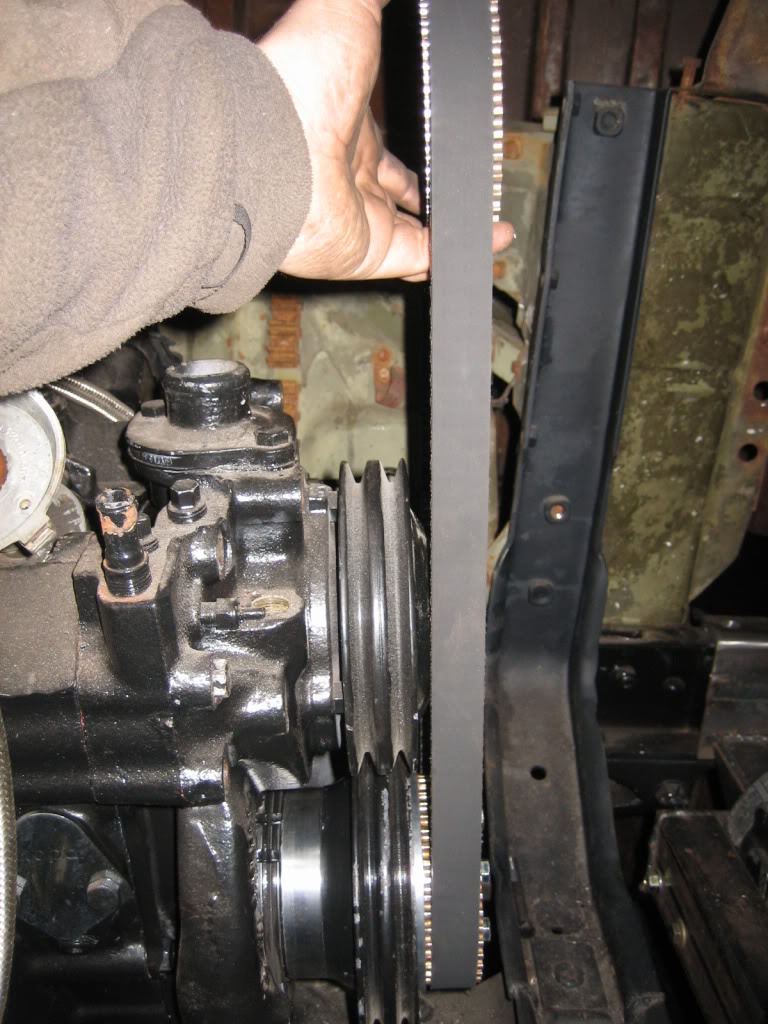
Old timing belt off my escort, way, way too long, will need to get something shorter:
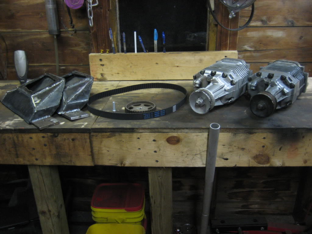
the ladies and their manifolds:
also finished welding the doghouse up. Need to knock the welds down, put a little mud on it, and it will be ready for paint. That is the last of the major body and rust repair. now it is just stripping and dent bumping.
2 1/2 months later...
The Blower hub is DONE!!!
He made one small booboo... The 6 larger holes drilled to take mass out he didn't drill on the proper centerline, so they came really, really close to breaking out on the inside bore, but, it's OK down on the end that mates to the crank, so, I asked for a nice discount and took it as-is rather than making him make another one.
From this:
To this:
Crank position ring not pressed all the way down. Will do that once I figure out how I want to mount the position sensor:
Beef baby, Beef:
mounted:
Old timing belt off my escort, way, way too long, will need to get something shorter:
the ladies and their manifolds:
also finished welding the doghouse up. Need to knock the welds down, put a little mud on it, and it will be ready for paint. That is the last of the major body and rust repair. now it is just stripping and dent bumping.
Thread Starter
1.0 BAR
Joined: Feb 2003
Posts: 461
From: Wisconsin
more work done. Tore the front end down to get the blocks out from under it. Got a good deal on another forum on 3 pair of matching leaves. Added those to the pack, and with the increased stiffness and arch, I think it will ride at or close to where it was with the blocks:
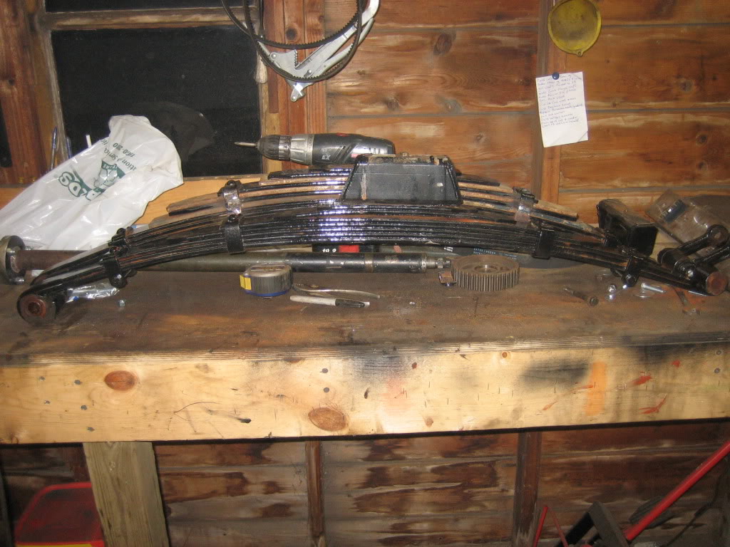
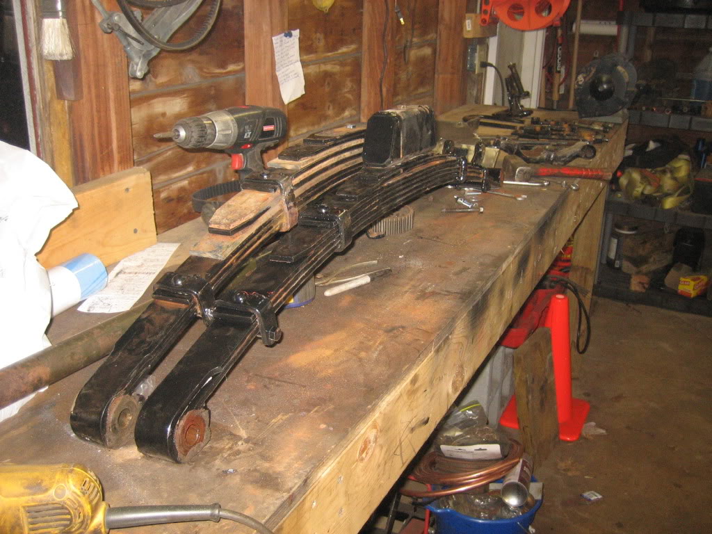
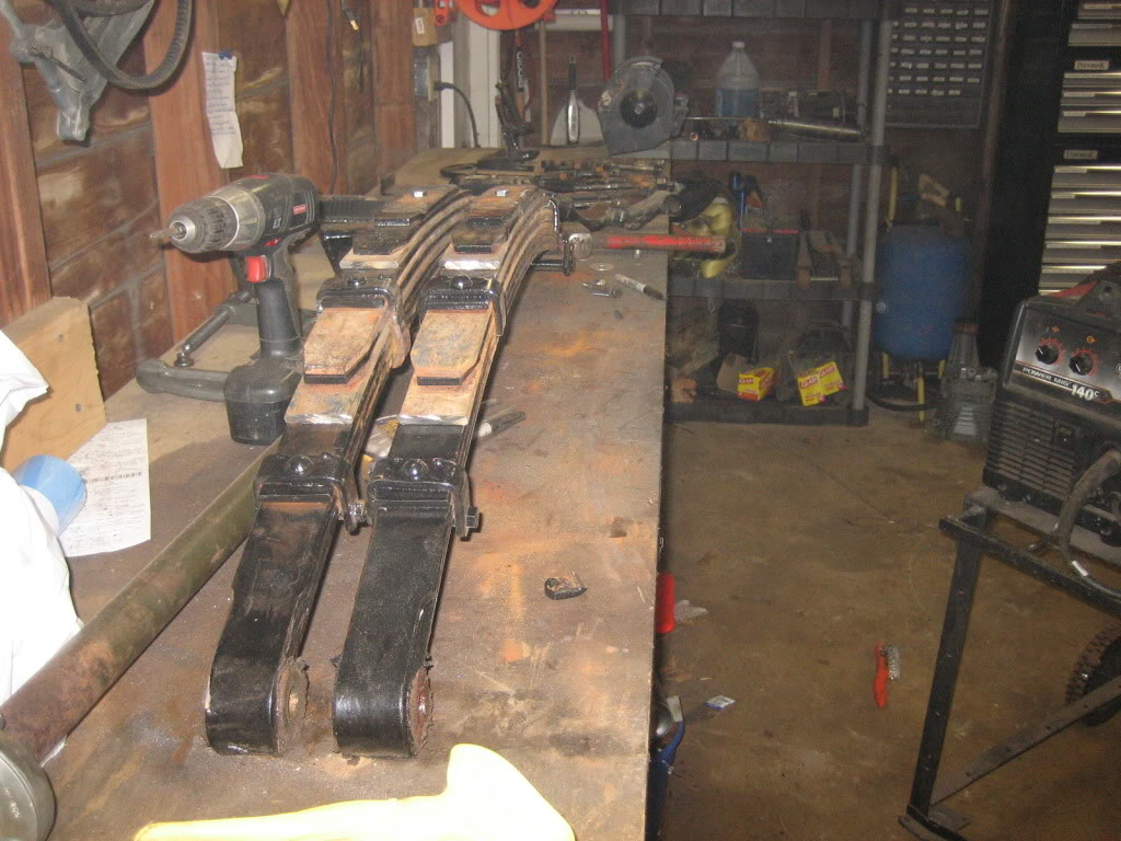
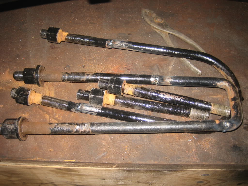
Gotta get new, shorter U bolts now, as well as some new bushings and pins. The drivers side front pin was pretty tired, and the passengers front bushing was tired, so, I ordered a new set of both to go all the way around.
Gotta get new, shorter U bolts now, as well as some new bushings and pins. The drivers side front pin was pretty tired, and the passengers front bushing was tired, so, I ordered a new set of both to go all the way around.
Thread Starter
1.0 BAR
Joined: Feb 2003
Posts: 461
From: Wisconsin
no pictures, as it wasnt that exciting, but, more progress:
Finished rebuilding the power steering pump, and I put the remote reservoir backing plate on it. I then cleaned and stripped the remote reservoir tank. Got it off a snow plow truck at the junkyard, should have lots of capacity for the tie rod bydraulic assist cylinder I'm running.
Also finished the few little things I had to do for the front winch mount, so, Once I get that sandblasted and painted, I can button that one up, and scratch it off the list.
I then tore down both M90 blowers. Both were in overall good shape, with average wear for the miles on them. Both are in need of new couplers, an oil change, and a repacking of the bearings, but, that is pretty standard for used M90s.
Thread Starter
1.0 BAR
Joined: Feb 2003
Posts: 461
From: Wisconsin
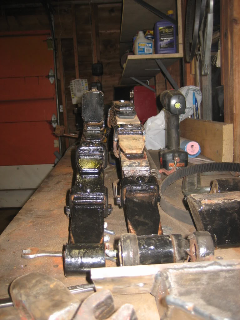
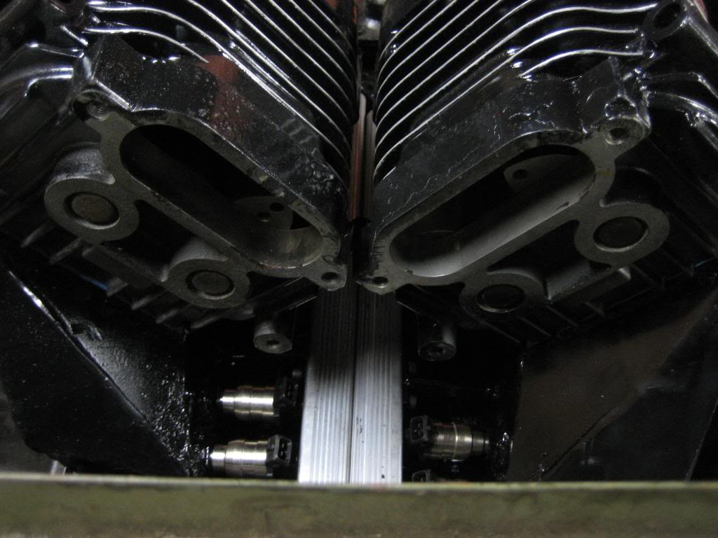
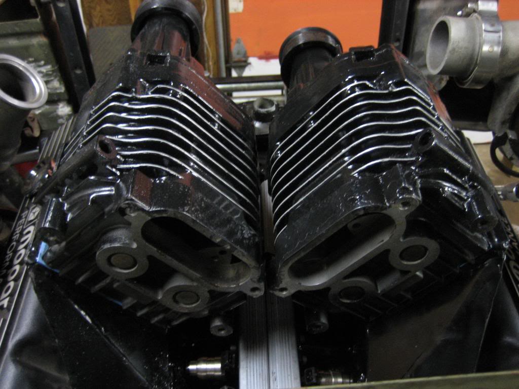
rebuilt the blowers with new seals, repacked the bearings, new oil, and new couplers. Turn like they are brand new. Also threw some paint on them so they match the rest of the underhood, and sanded out the fins so they blend with the finned valve covers:

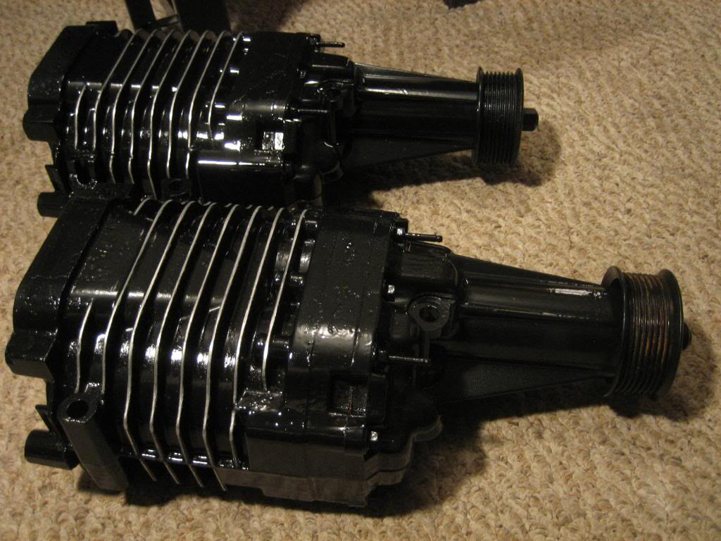
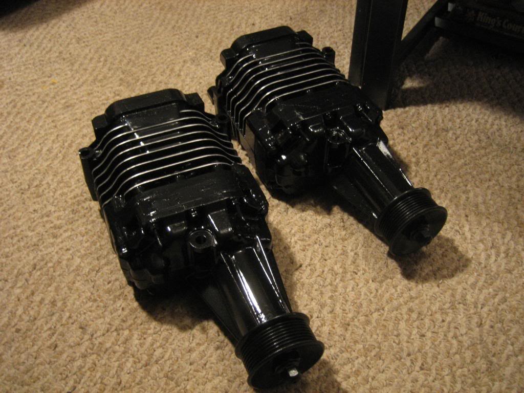
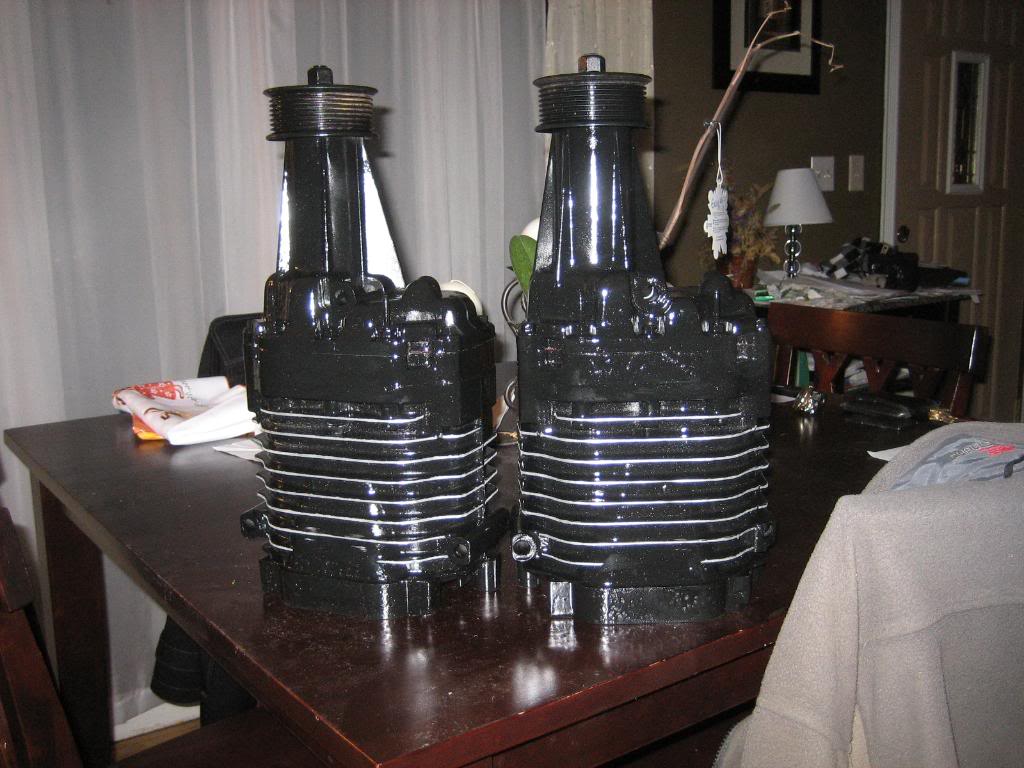
Ordered some more parts as well. Wiring harness will be here tomorrow, as well as the rest of the stuff to do the hydraulic clutch. Ordered fuel rail stock, and injectors. Got a set of eight 83 lb/hr injectors. That should be enough fuel to make at least 7-800 ponies :shock: Once those get here, I can install them in the plenums, and bolt the blowers and plenums down permanently! Then it is full speed ahead with the blower belt drive setup.
Ordered some more parts as well. Wiring harness will be here tomorrow, as well as the rest of the stuff to do the hydraulic clutch. Ordered fuel rail stock, and injectors. Got a set of eight 83 lb/hr injectors. That should be enough fuel to make at least 7-800 ponies :shock: Once those get here, I can install them in the plenums, and bolt the blowers and plenums down permanently! Then it is full speed ahead with the blower belt drive setup.
Thread Starter
1.0 BAR
Joined: Feb 2003
Posts: 461
From: Wisconsin
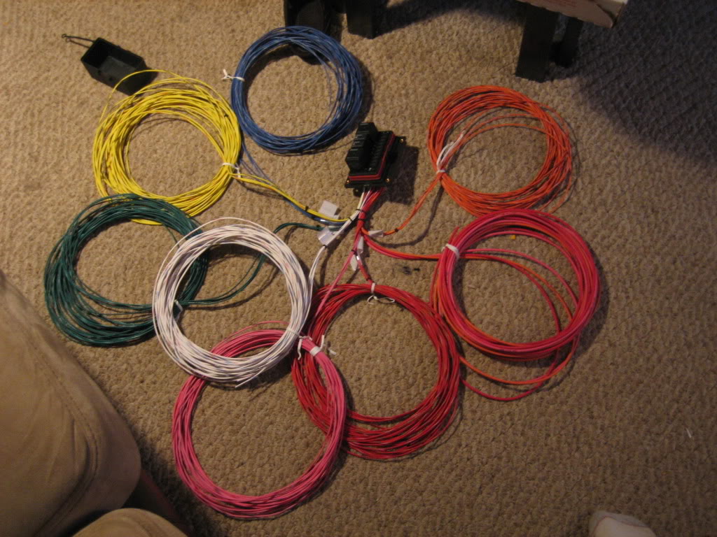
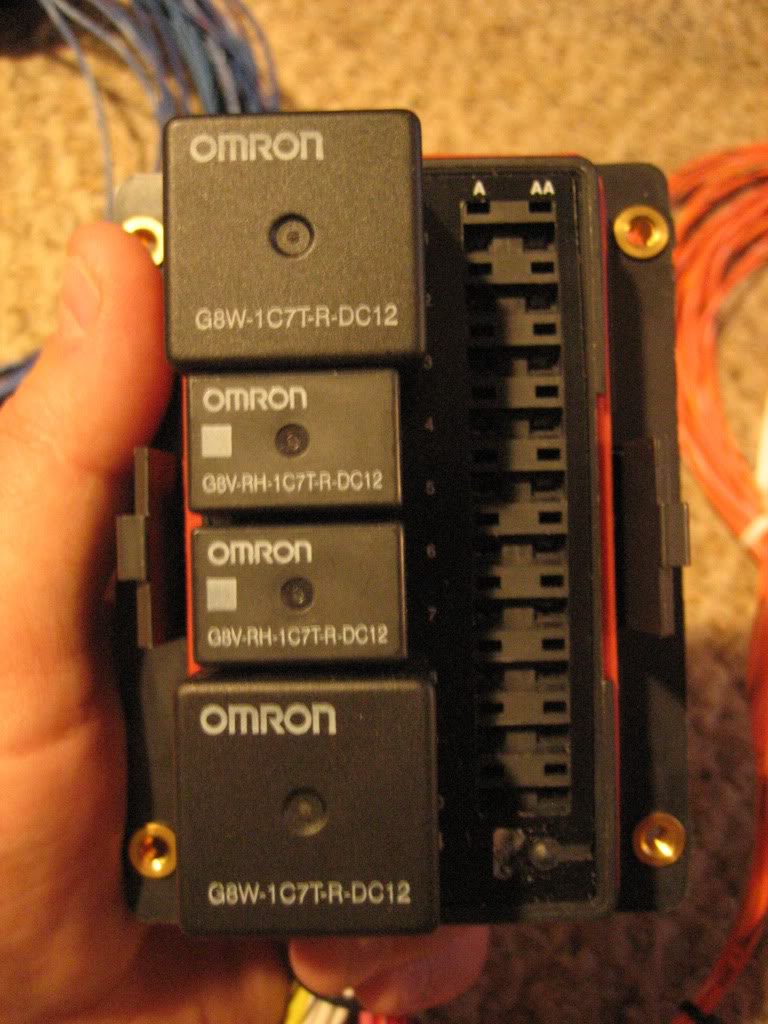
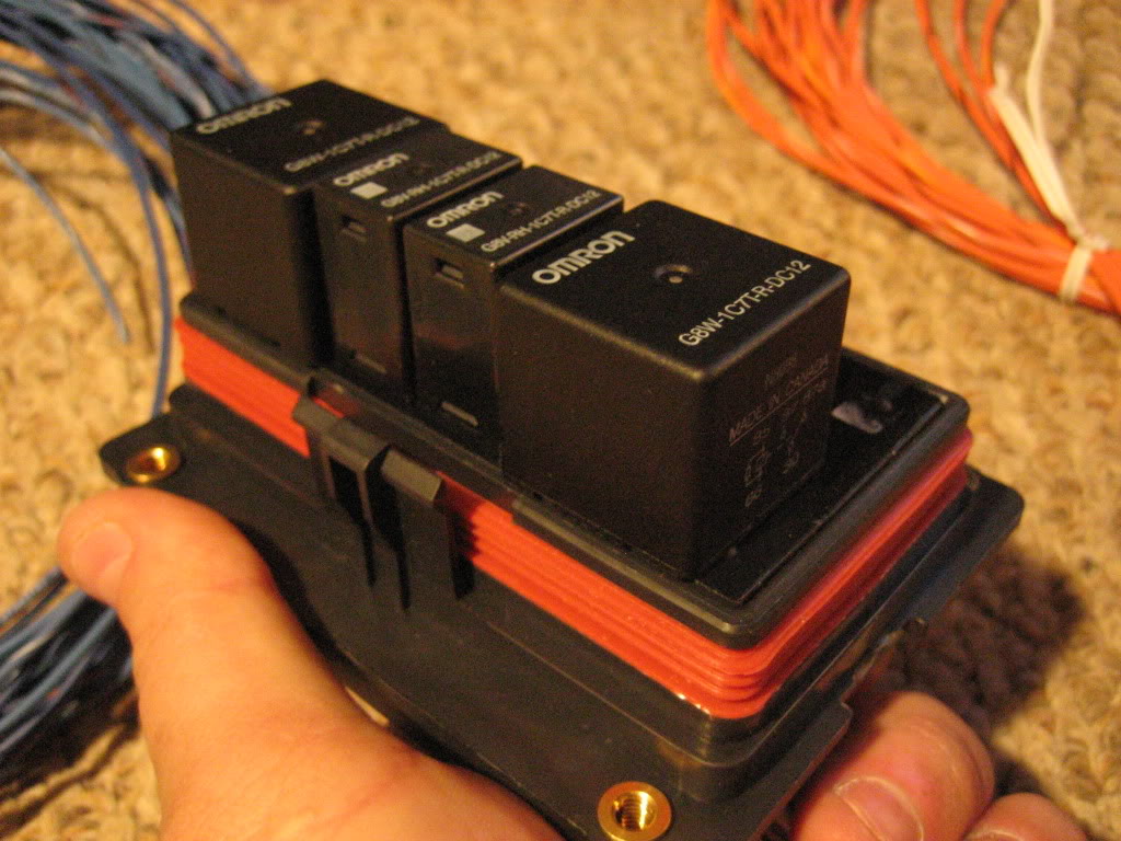
Got the harness today. EXCELLENT piece. I work daily with automotive grade wiring where I work and this is some of the best quality I have seen. I think the wire is either SXL or GXL, either of which being a very good grade of wire. The fuse box is completely waterproof, all of the wires have rubber weatherpack seals on them, and the cover clips on with a multiple rib seal. It seals so well it actually takes a few seconds for the air to seep out from the seals so you can push the cover down completely.
Wire leads are very generous. I didn't measure, but they have to be at least a 20' run on each. The fuses are divided up into 3 separate main circuits, with it being 3 circuits on two leads, and 4 on the third instead of one common bus like what is normally done. This is a nice feature, as it will allow me to taylor how the power is fed into the fusebox. They can be hardwired to B+, or, switched through the key, or, relay operated NC, or relay operated NO.
It also has 4 relayed high amperage circuits, a pair of 40 amp relayed circuits, and a pair of 20 amp circuits. Came with 4 high vibration waterproof resetting circuit breakers for those. Included a nice 8 gauge 140 amp alternator lead, a bunch of terminals and lugs and leads, and a 100 amp primary fuse, as well as brackets, zip ties and hardware to mount it to the cab. Finally, they included a sample of their powerbraid wire loom, which I am impressed with and will most likely order to do all of my wire wrapping.
Thread Starter
1.0 BAR
Joined: Feb 2003
Posts: 461
From: Wisconsin
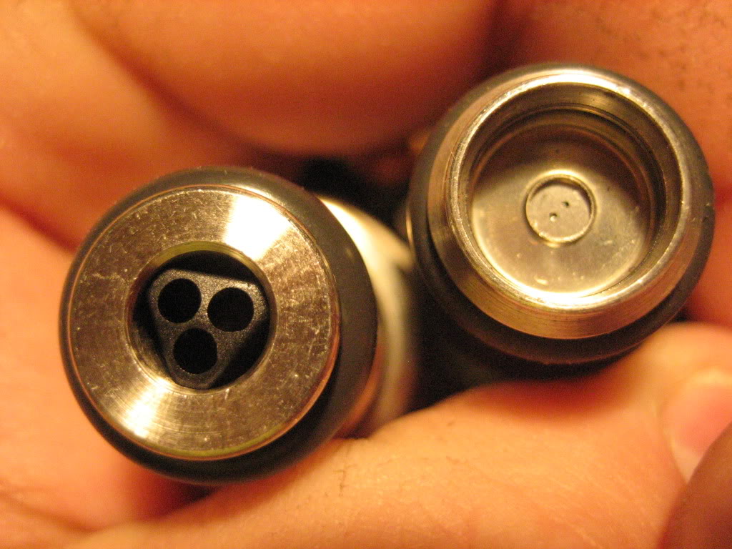
This is a normal 15 lb/Hr 2 liter 4 cylinder car injector. fuel comes out the two little holes:
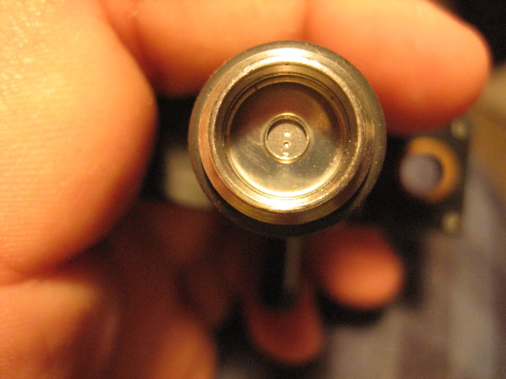
This, is one of my new 83 lb/hr injectors for the truck:

Finally, let's compare the two side by side: :shock:
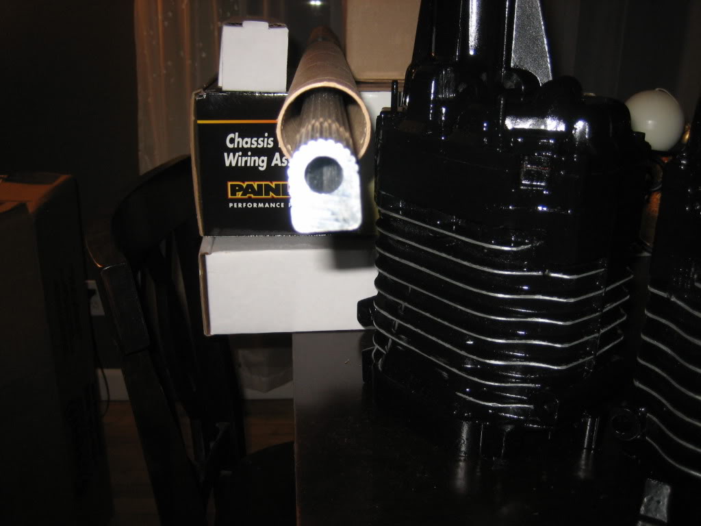
Fuel rail material:
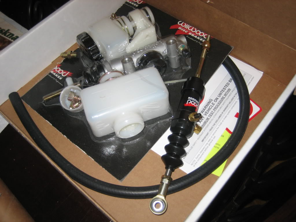
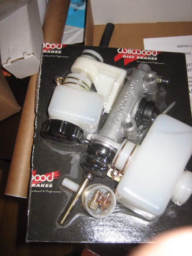
self adjusting, remote mount reservoir clutch kit. thing out of the package laying in the box is the slave cylinder:
This, is one of my new 83 lb/hr injectors for the truck:
Finally, let's compare the two side by side: :shock:
Fuel rail material:
self adjusting, remote mount reservoir clutch kit. thing out of the package laying in the box is the slave cylinder:
Thread Starter
1.0 BAR
Joined: Feb 2003
Posts: 461
From: Wisconsin
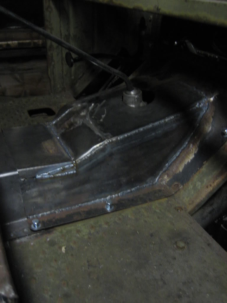
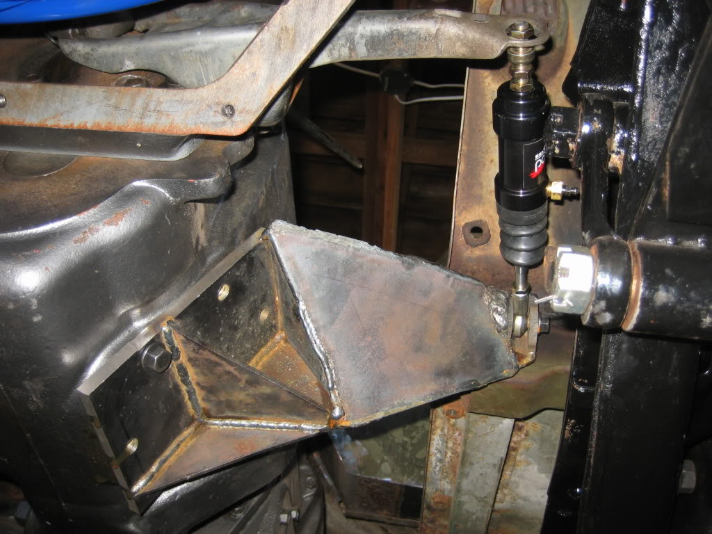
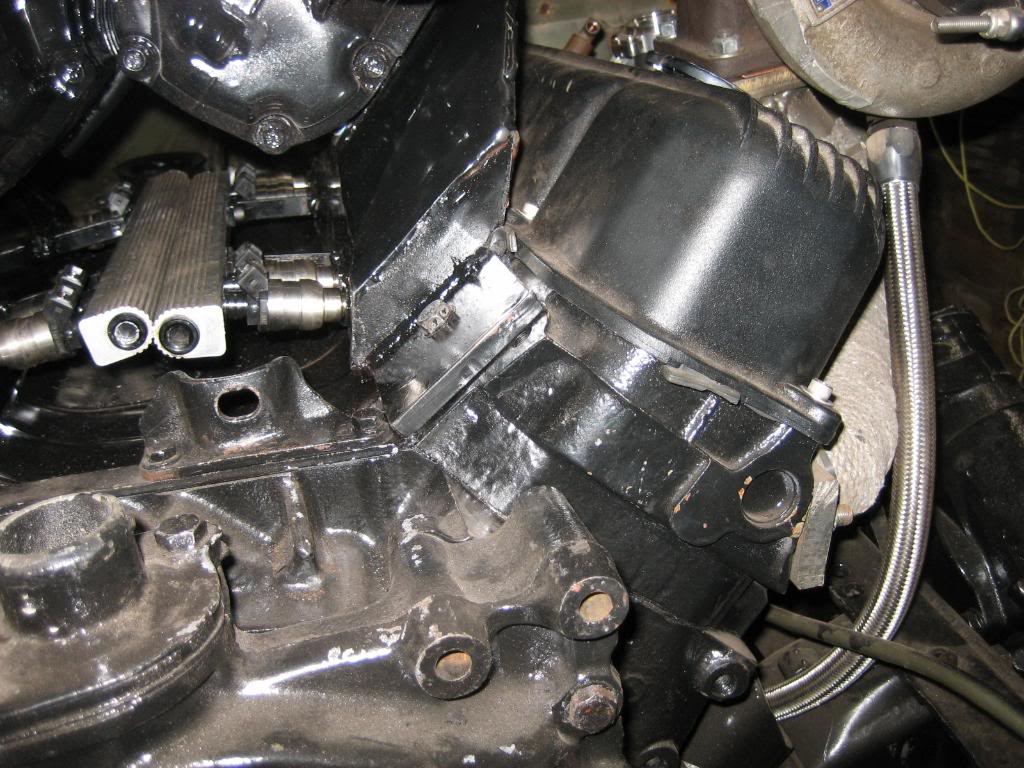
got some work done on the clutch. Made a bracket that comes off the PTO port on the trans for the slave to pull off of for the fork. 3/8" base plate (had the steel laying around) then 1/8" plate boxed into a triangular structure. Just clears the floorboard and keeps the slave in good alignment. I need to take the fork out and weld a chunk of steel into the hole with a countersink into it as the ball that came on the slave is too small and fits right through the current hole. I looked for the metal part that fits into the hole OEM but I can't seem to find the one I had and they can be a PITA to find in the boneyard.
looking up:
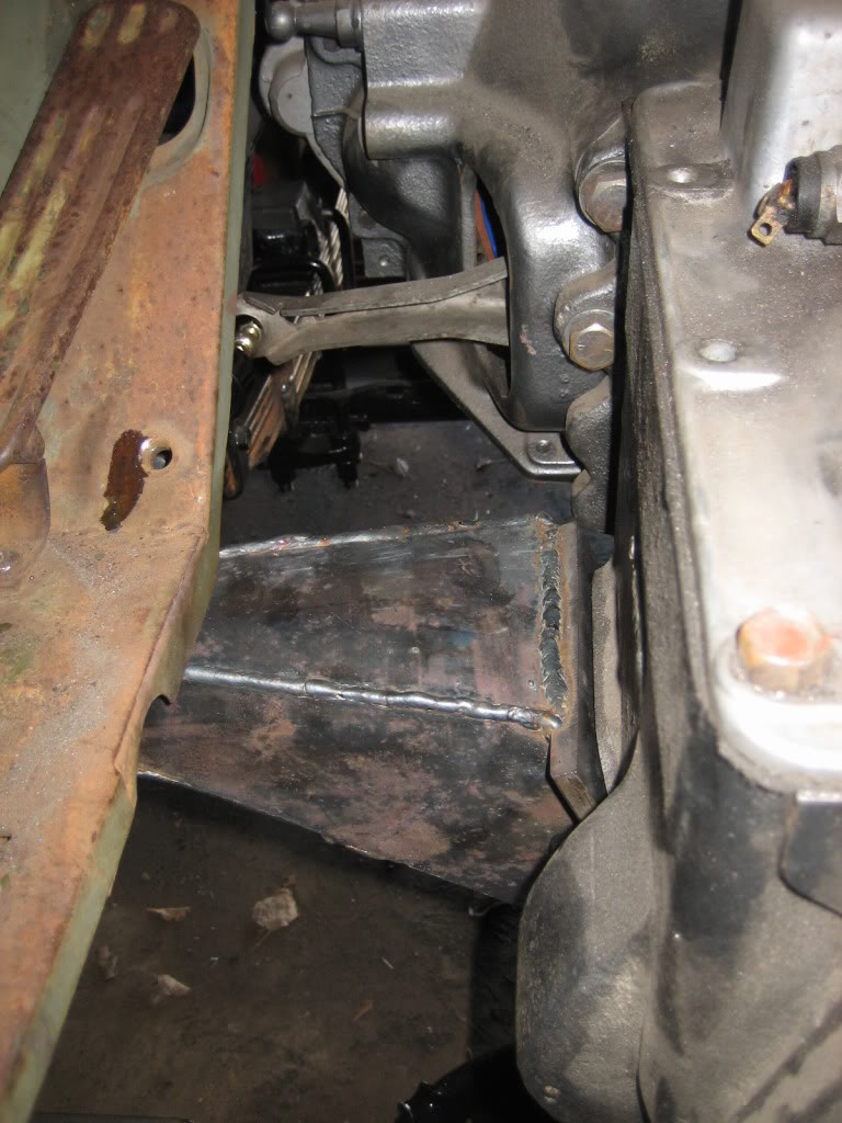
looking down from drivers seat:
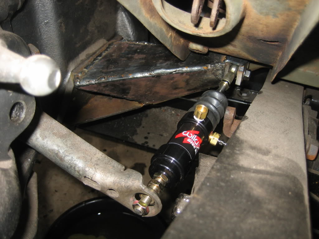
drivers frame rail view:
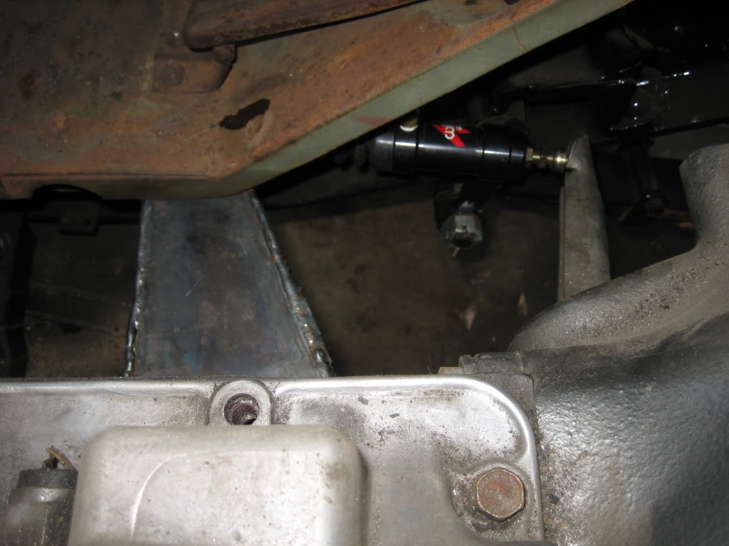
passenger's side view:
looking up:
looking down from drivers seat:
drivers frame rail view:
passenger's side view:
Thread Starter
1.0 BAR
Joined: Feb 2003
Posts: 461
From: Wisconsin
finished the slave mount, but didn't take any pics of it. It fits nice. Got to make the master cylinder mount next. I made a new lever arm for the clutch pedal shaft that reverses the direction so I can mount the new MC behind the pedal, instead of in front of it.
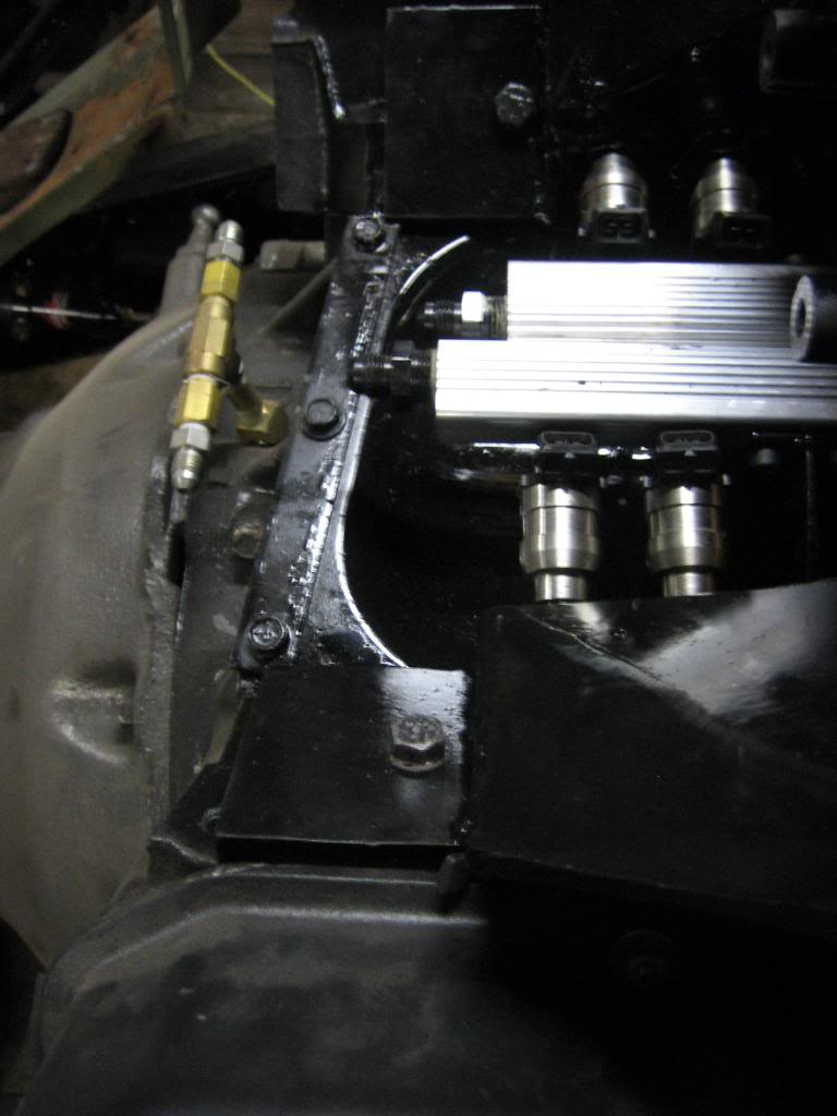
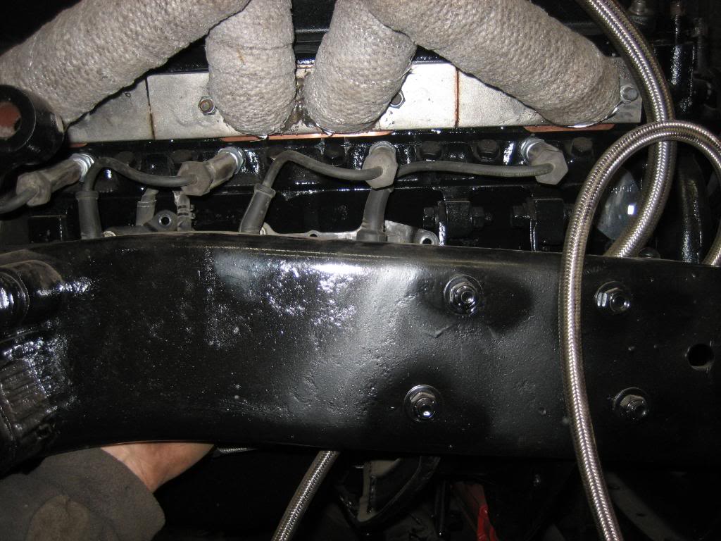
Been working on the EFI system, as well as the superchargers. Got in the last few parts I was wating on to install the blowers once and for all. Made my fuel rails, drilled out some nuts and welded them to the intakes for injector bosses, and then made little T shaped mounts to hold the rails to the manifolds. they BARELY cleared one another!!
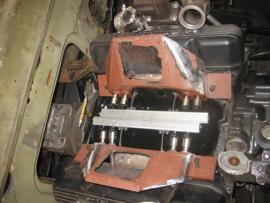
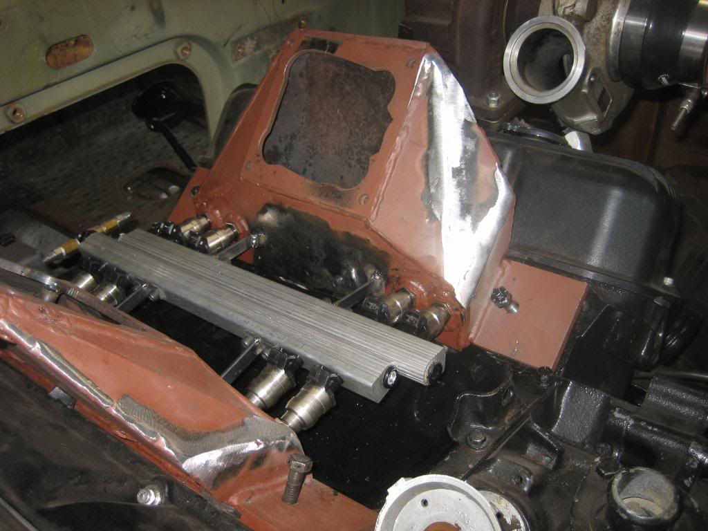
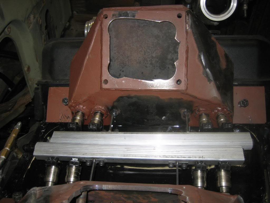
and, all installed:
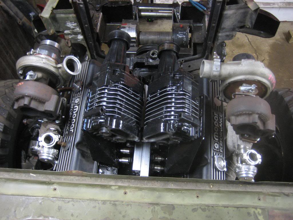
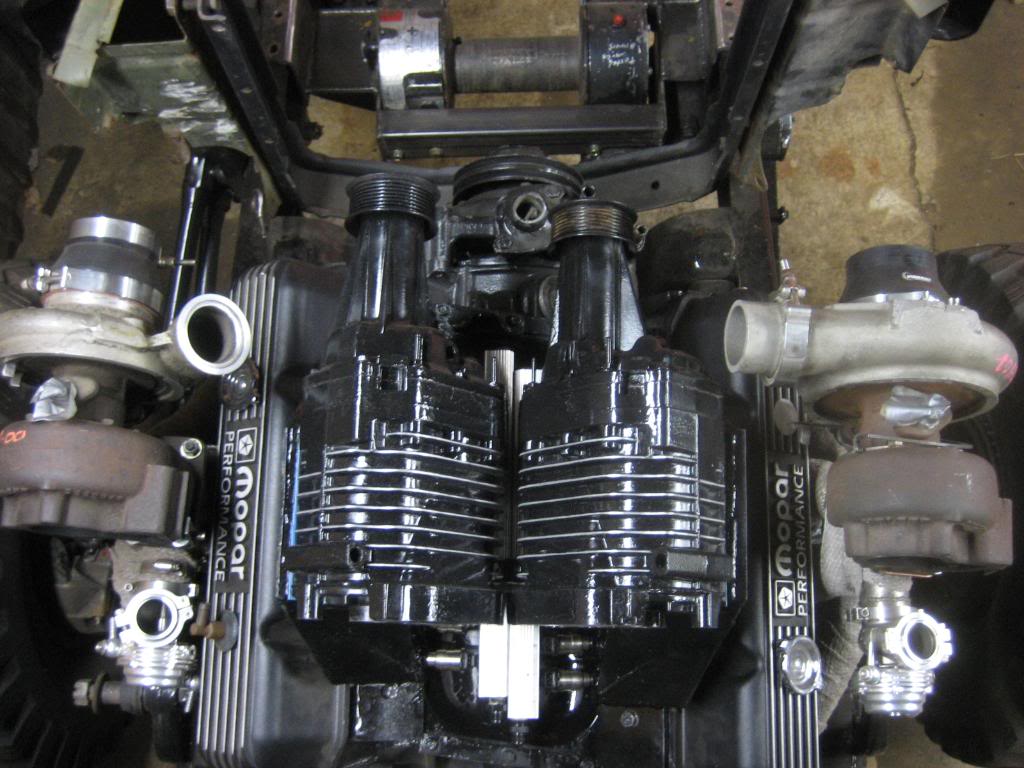
See, just fit past one another... Whew!!

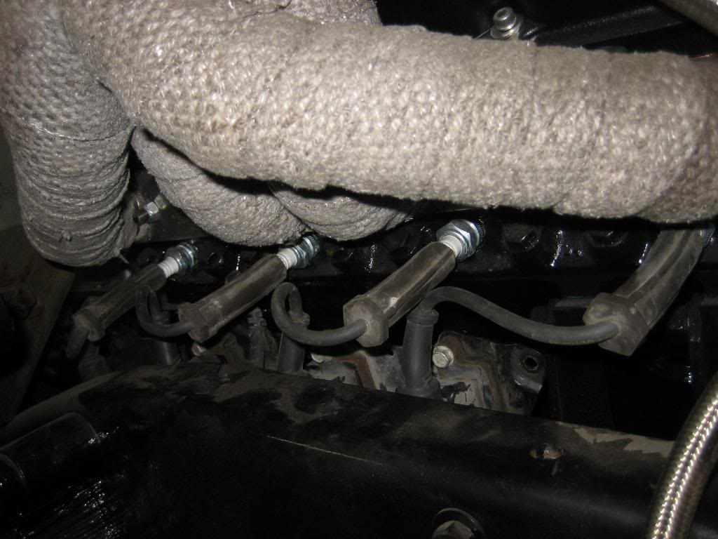
Pointing right down the port throat at the intake valve:
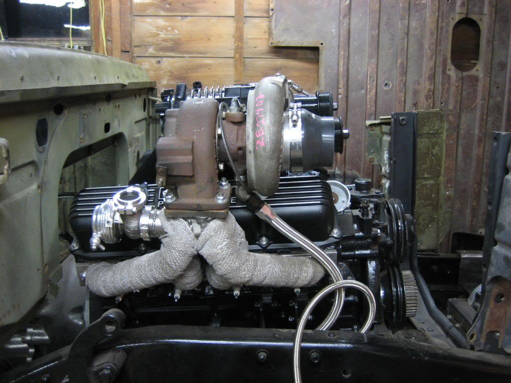
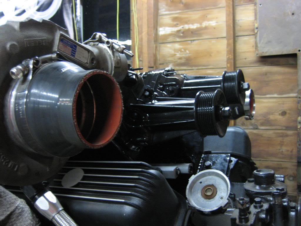
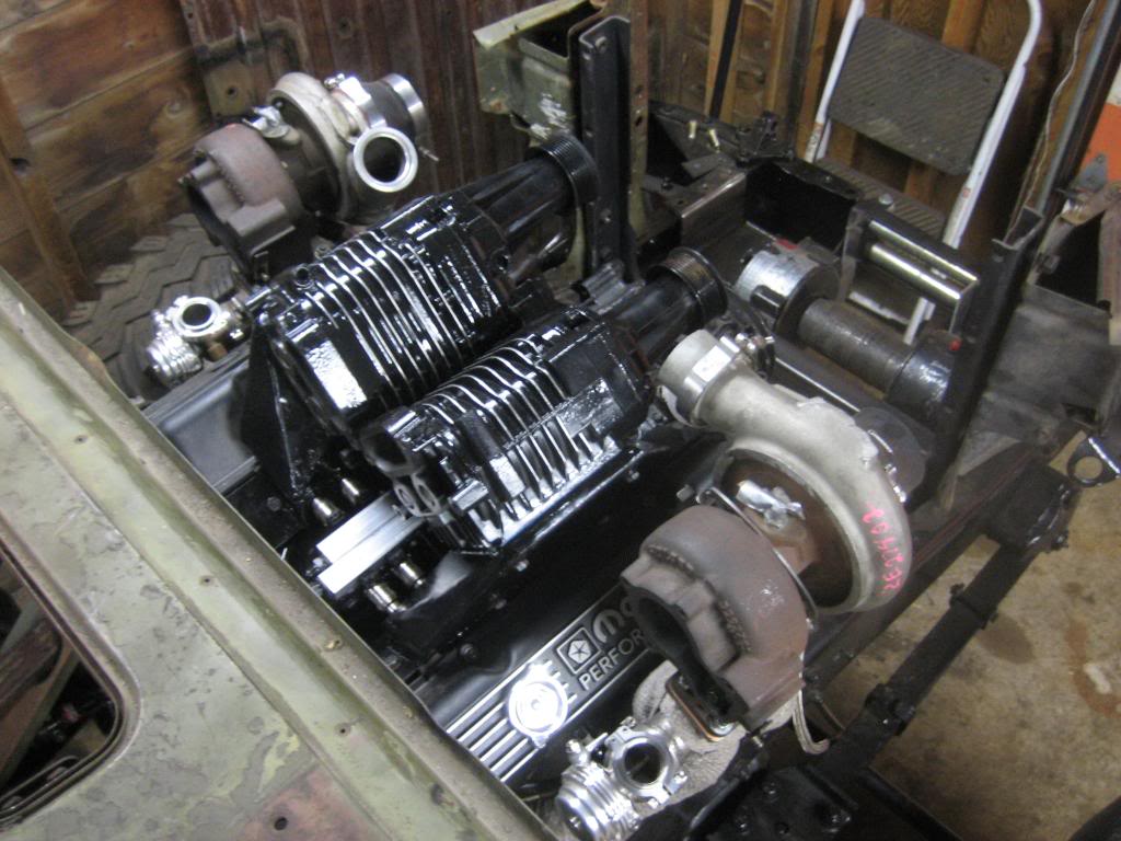
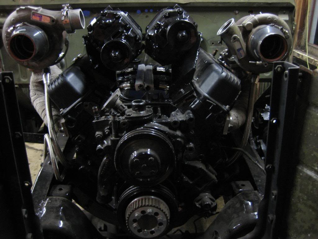
Need to build a backing plate for the charge pipes from teh turbos to weld to, as well as to tie the two blowers together to give them more strength:
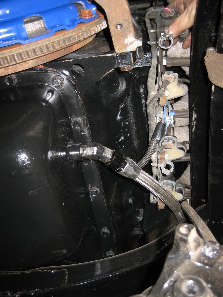
fittings just clear, and come out side by side. There will be two Walbro GLS392 pumps, good to 500 HP each on an EFI system, with duel regulators, and dual feeds and returns. She's gonna have one SERIOUS fuel system!
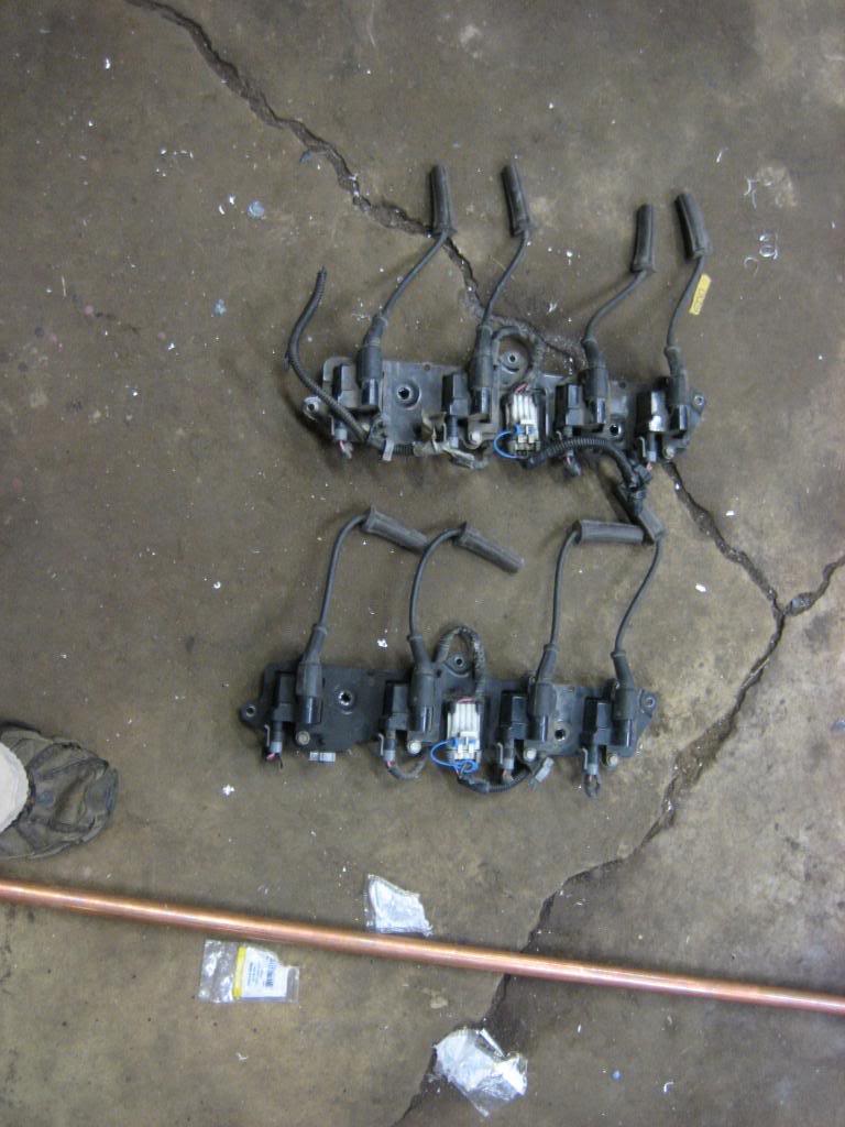
Scrounged a new boneyard yesterday and found some GM LS1 car coils. Not as fire breathing as the LS2 truck coils, but, they have no trouble lighting cylinders under 30 PSI of boost, so they should do just fine for what I plan to do with them. Got a decent deal on them too. I plan on mounting them upside down beside the block. Will modify the mounting backet to bolt to the motor mount and the bellhousing, then it's as simple asrunning them up to the plugs, and they should just clear the fender splash pans.


Been working on the EFI system, as well as the superchargers. Got in the last few parts I was wating on to install the blowers once and for all. Made my fuel rails, drilled out some nuts and welded them to the intakes for injector bosses, and then made little T shaped mounts to hold the rails to the manifolds. they BARELY cleared one another!!
and, all installed:
See, just fit past one another... Whew!!
Pointing right down the port throat at the intake valve:
Need to build a backing plate for the charge pipes from teh turbos to weld to, as well as to tie the two blowers together to give them more strength:
fittings just clear, and come out side by side. There will be two Walbro GLS392 pumps, good to 500 HP each on an EFI system, with duel regulators, and dual feeds and returns. She's gonna have one SERIOUS fuel system!
Scrounged a new boneyard yesterday and found some GM LS1 car coils. Not as fire breathing as the LS2 truck coils, but, they have no trouble lighting cylinders under 30 PSI of boost, so they should do just fine for what I plan to do with them. Got a decent deal on them too. I plan on mounting them upside down beside the block. Will modify the mounting backet to bolt to the motor mount and the bellhousing, then it's as simple asrunning them up to the plugs, and they should just clear the fender splash pans.


