
Power Wagon Rebuild (Update: 11/5/08)


Thread Starter
1.0 BAR
Joined: Feb 2003
Posts: 461
From: Wisconsin
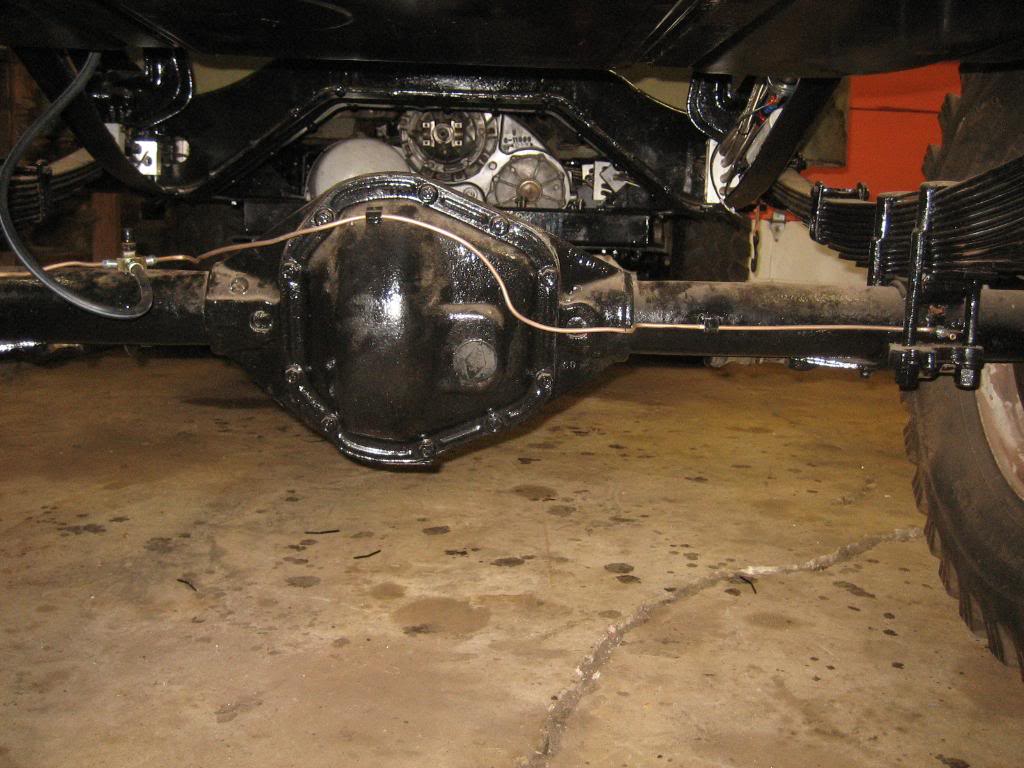
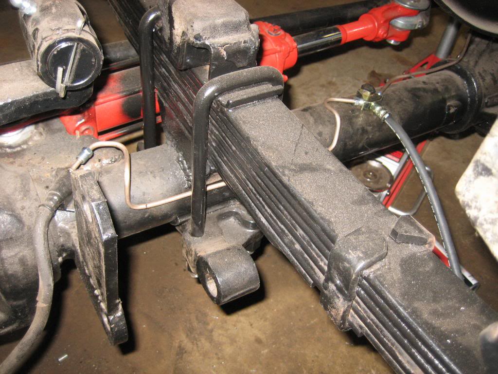
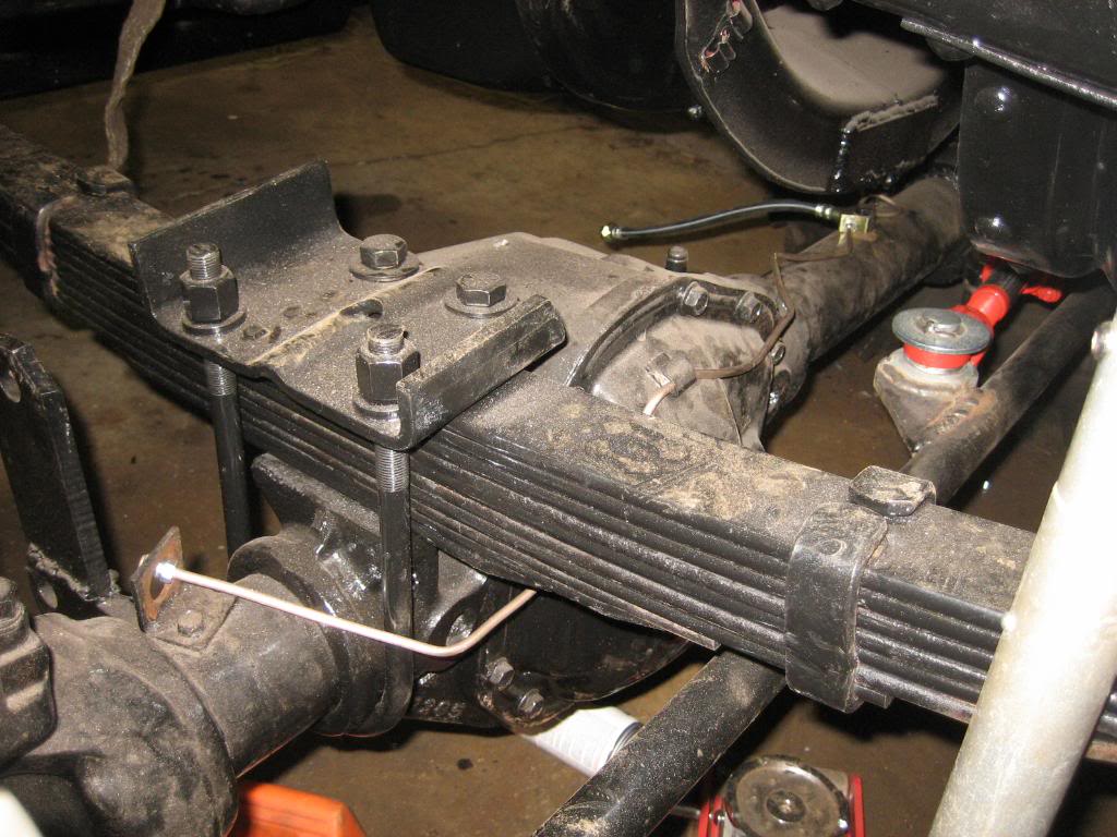
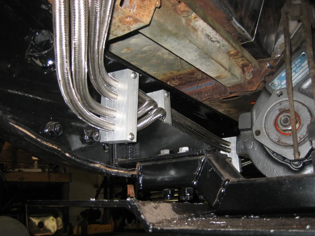
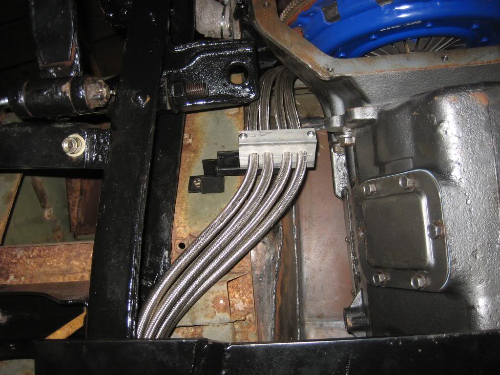
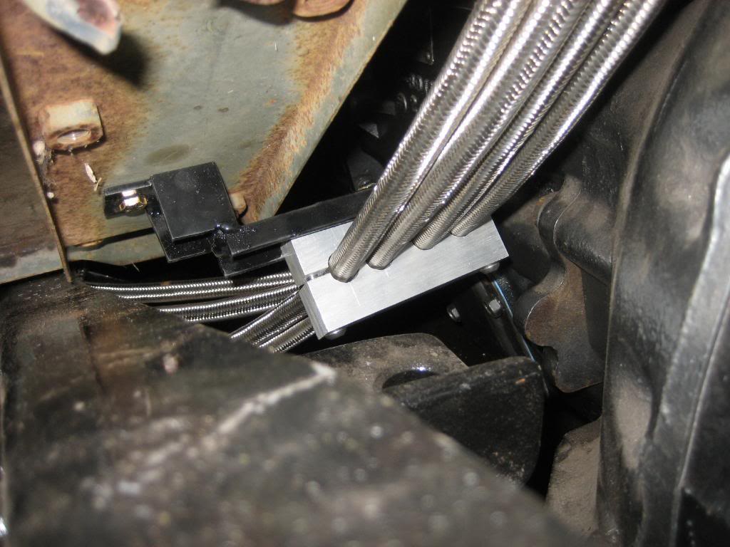
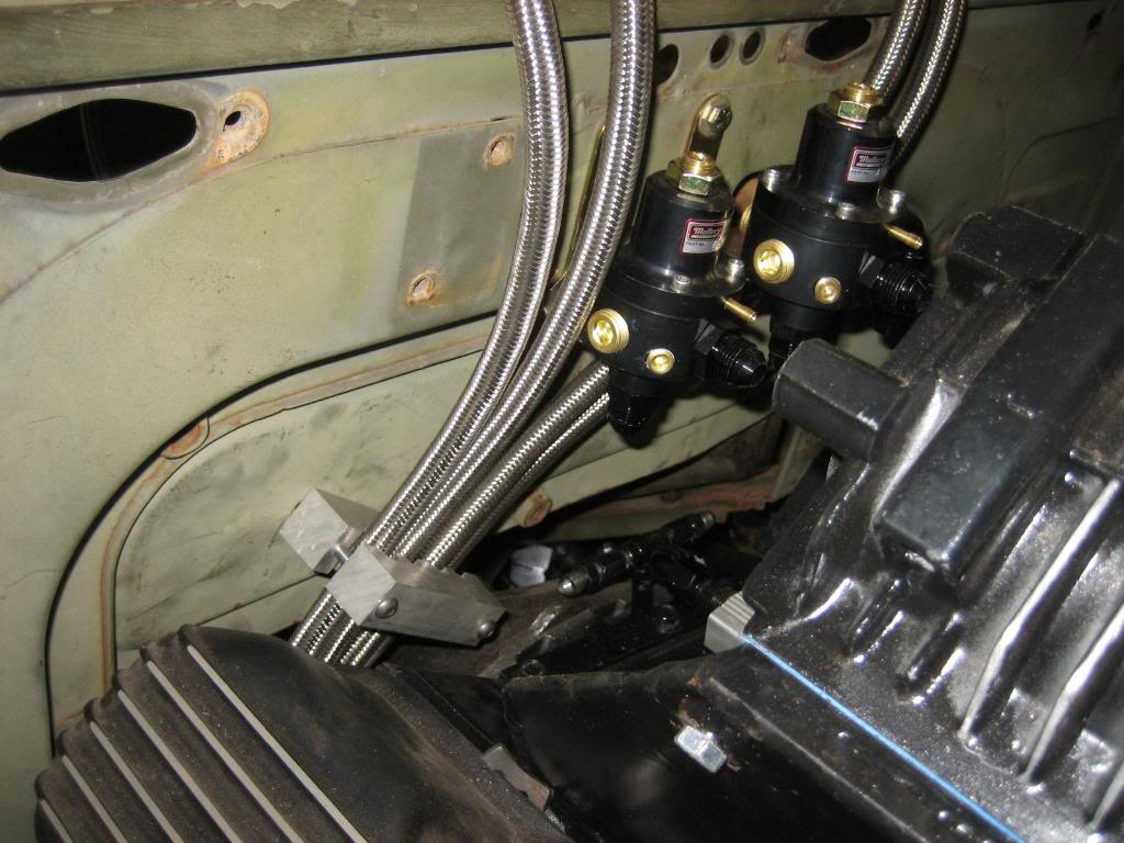
been a while since I posted, been tied up with other stuff, but, got the brake lines bent up and semi-mounted, as well as the fuel lines. I used Copper-Nickel-Iron brake line, made in Michigan. It's used by high end car companies like Audi, Saab, Porsche, M-B, etc as it does not rust, does not corrode, and is very workable. I could bend it easily by hand without kinking, and you can bend it 2-3 times before it starts to work harden.
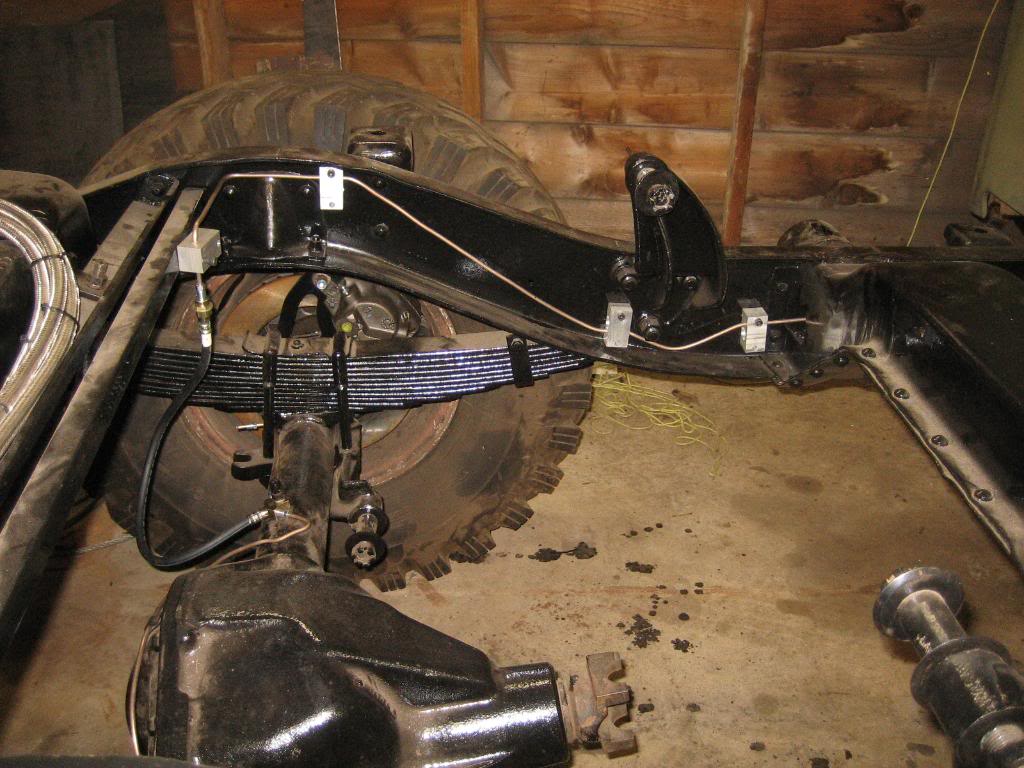
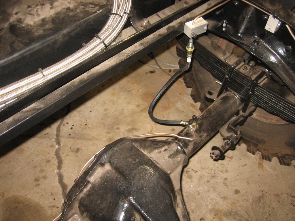
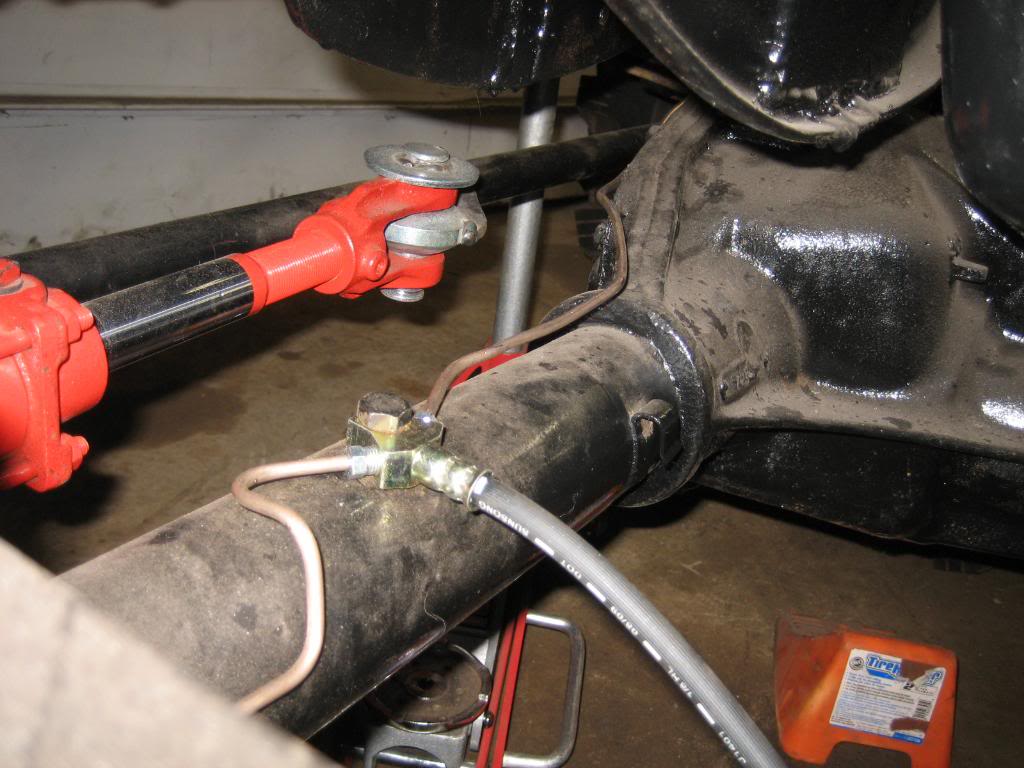
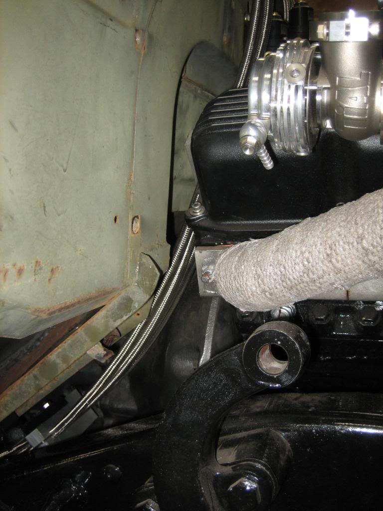
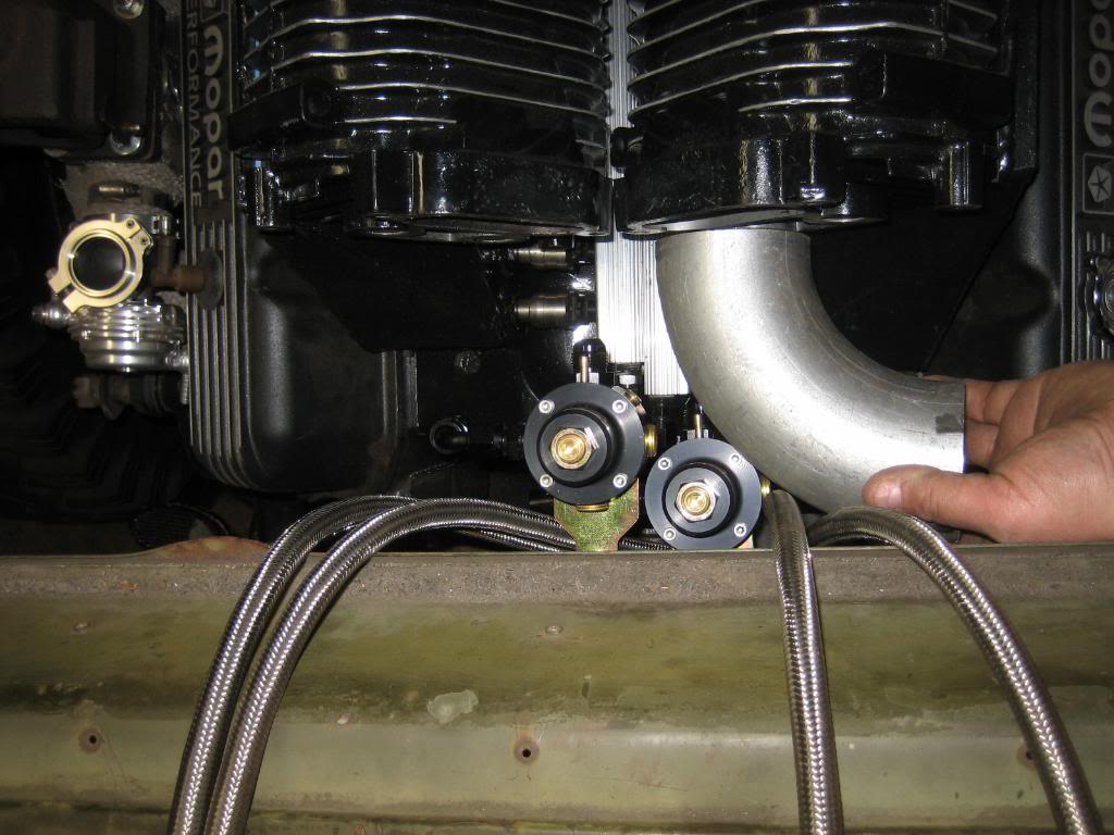
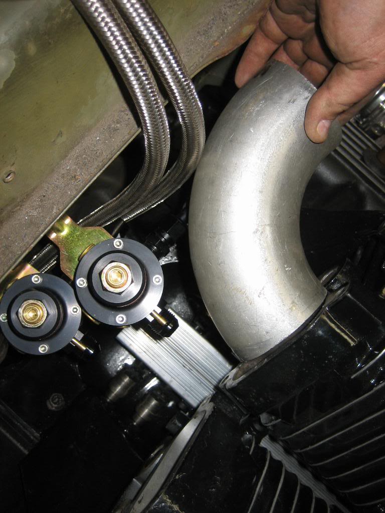
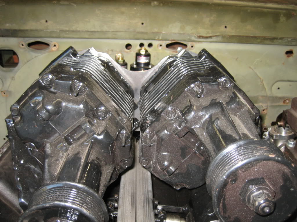
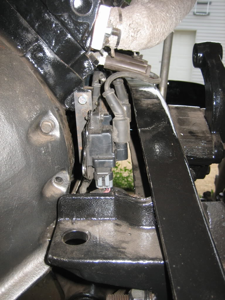
Took me a while to figure out where to stick the stupid fuel pressure regulators. Wouldn't go on the frame because they were too tall, couldn't mount them outboard on the firewall because of where the exhaust pipes will be... finally settled on the Vee between the blowers. VERY tight fit there, but if I get the tubes formed right for the blower inlets it should be alright.
Took me a while to figure out where to stick the stupid fuel pressure regulators. Wouldn't go on the frame because they were too tall, couldn't mount them outboard on the firewall because of where the exhaust pipes will be... finally settled on the Vee between the blowers. VERY tight fit there, but if I get the tubes formed right for the blower inlets it should be alright.
Thread Starter
1.0 BAR
Joined: Feb 2003
Posts: 461
From: Wisconsin
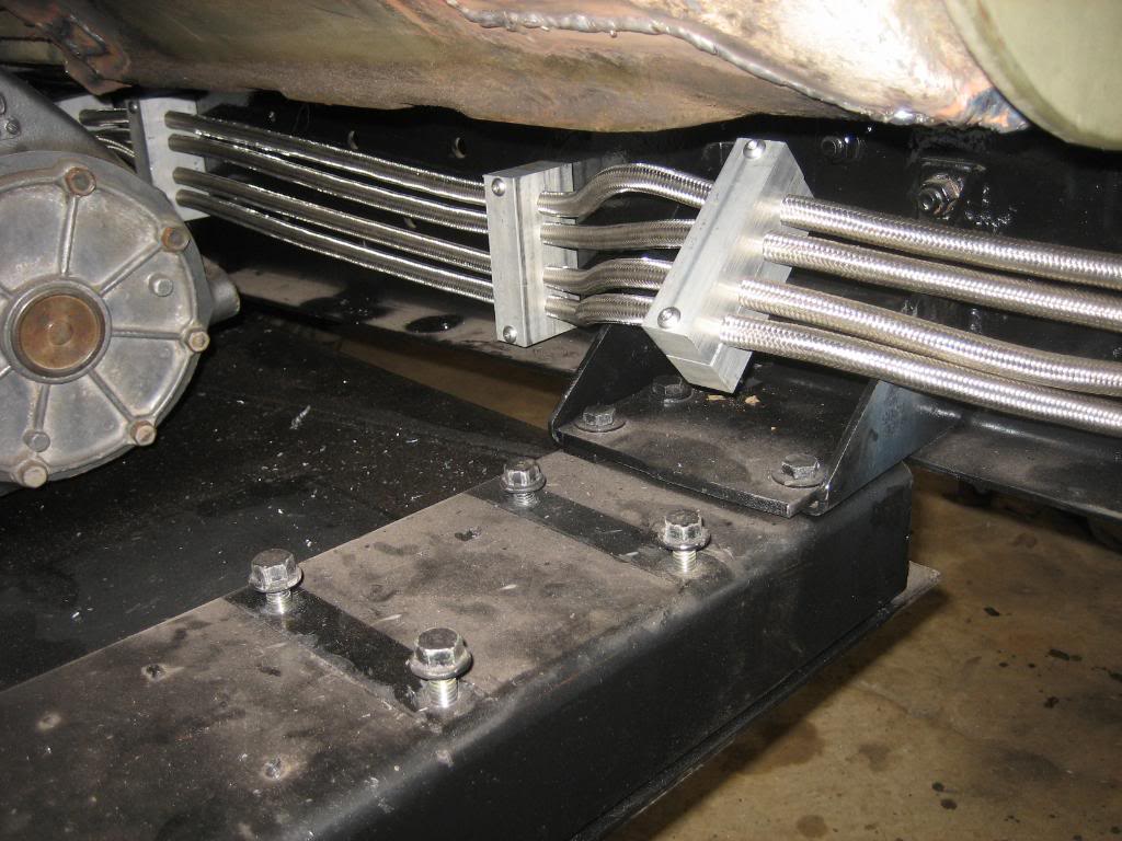
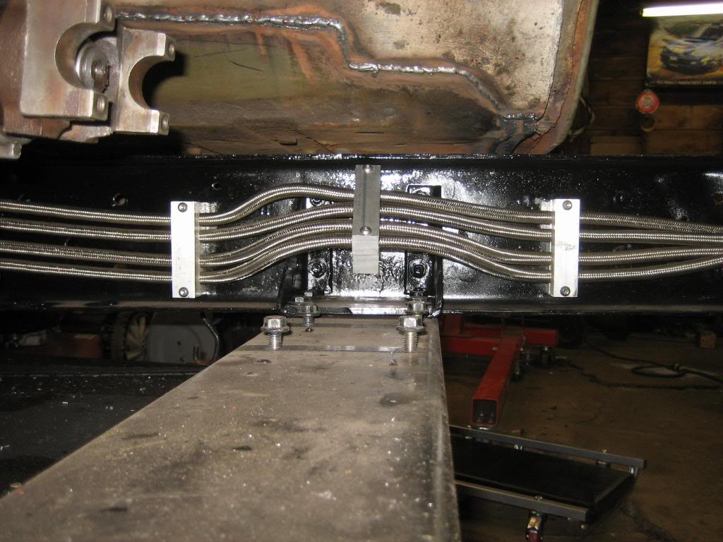
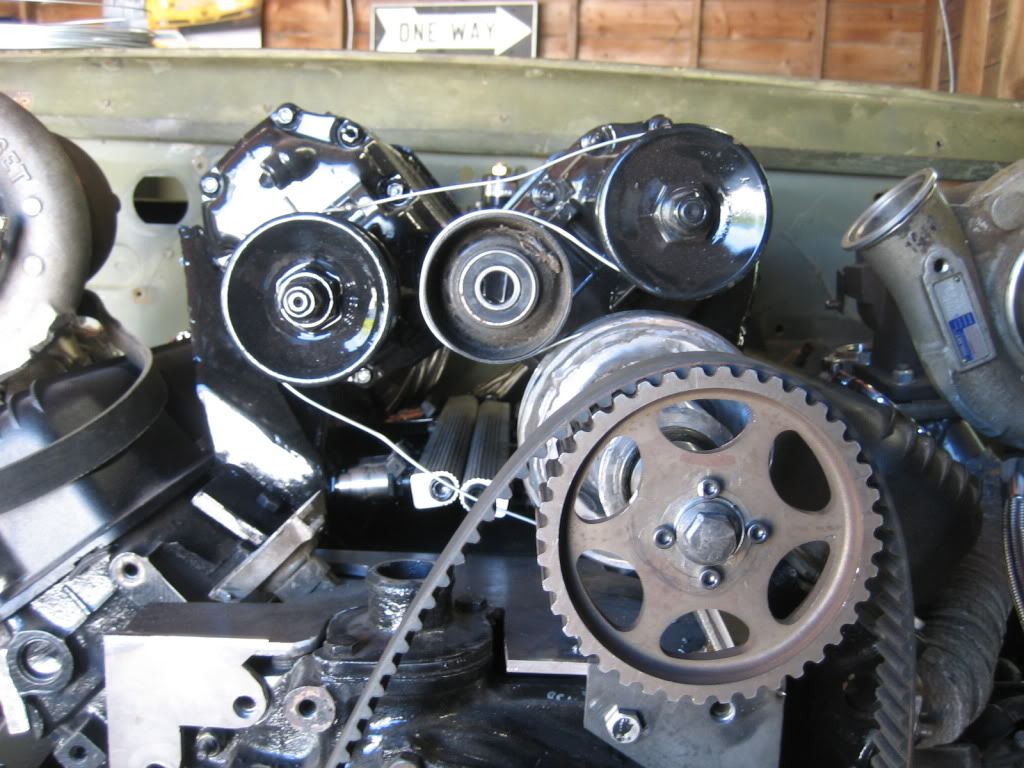
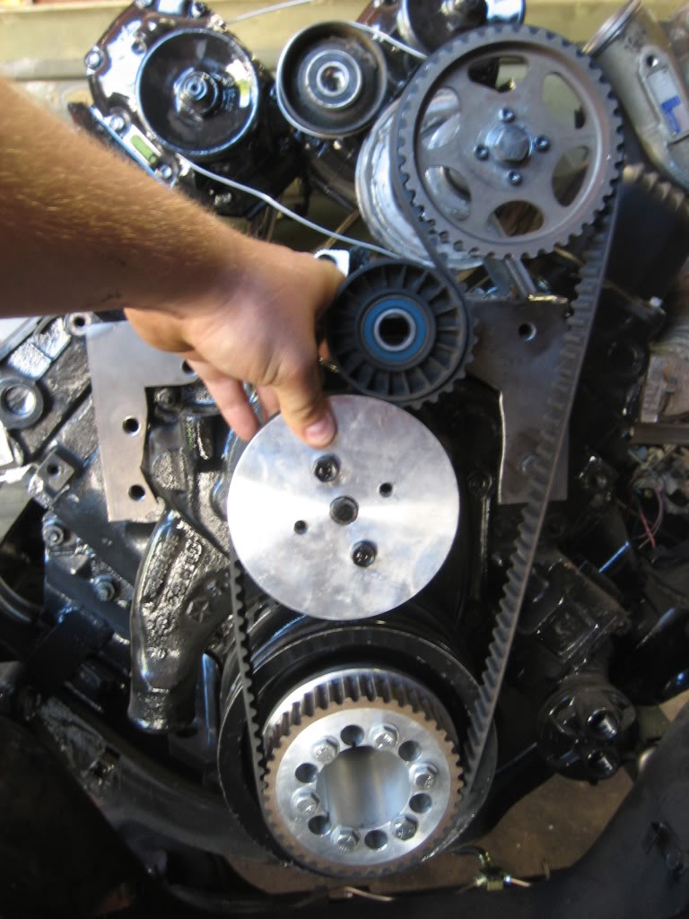
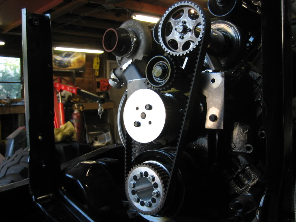
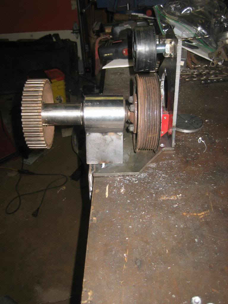
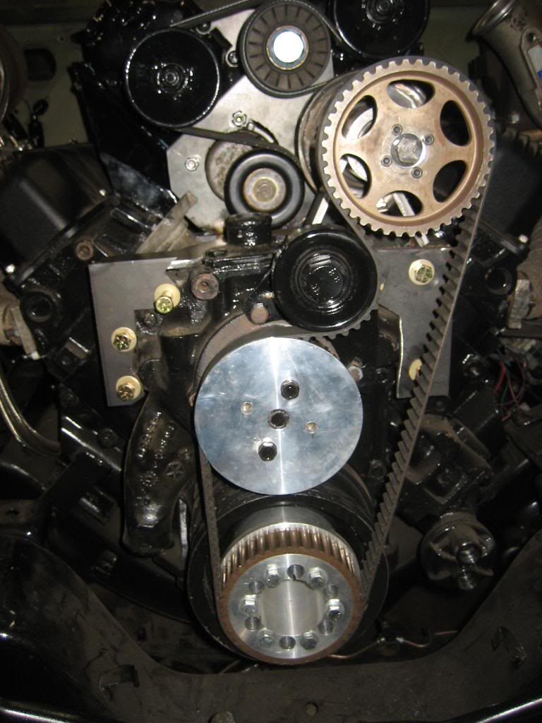
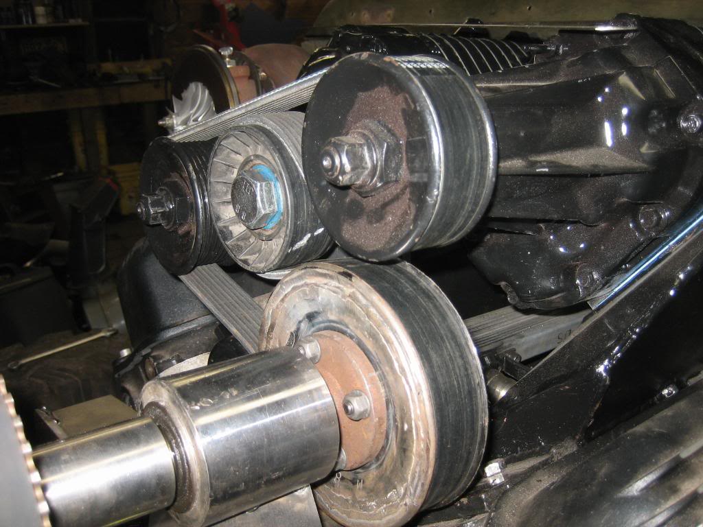
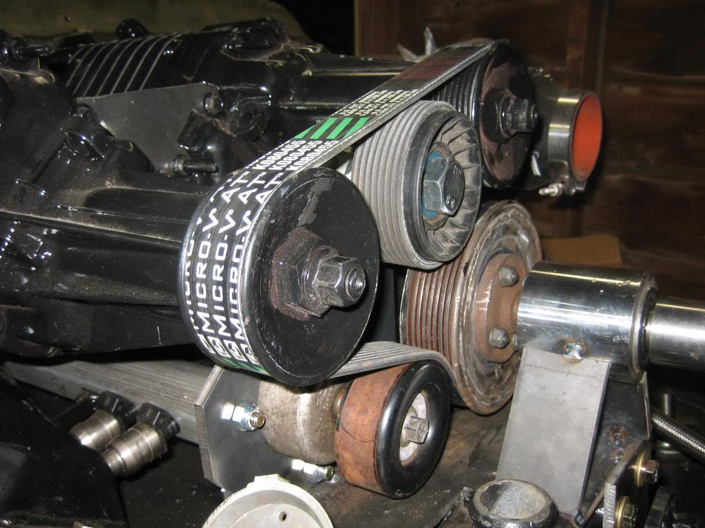
finalized the belt routing. Just need to finish the brackets. I had the excellent idea of driving the water pump with the cog belt which does several things for me:
1. Solid driven water pump. Gotta love that.
2. Alows me to hard mount the PS pump, and then make my adjustments at the alternator. Can run dual belts around both, and end up with one V belt adjustment, instead of two.
3. Alows me to lean the jackshaft off to the drivers side, which makes getting to the water neck a heck of a lot easier, and also alows me to get significantly more wrap on the serpentine belts.
4. Serp idler pulley in the middle will be hard mounted, while the tensioner will be on the bottom where there is no chance of inducing slip in the belt on the blowers from idler fluctuations.
5. Uses a standard goodyear belt, number 4080455.
Thread Starter
1.0 BAR
Joined: Feb 2003
Posts: 461
From: Wisconsin
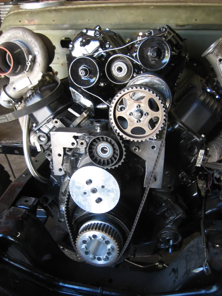
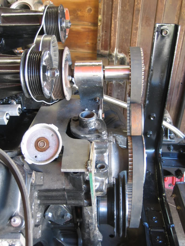
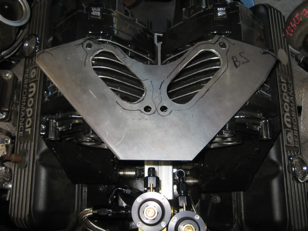
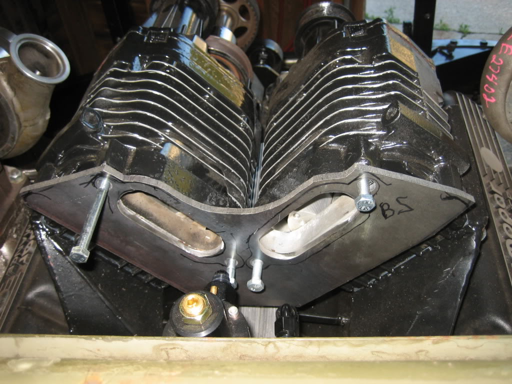
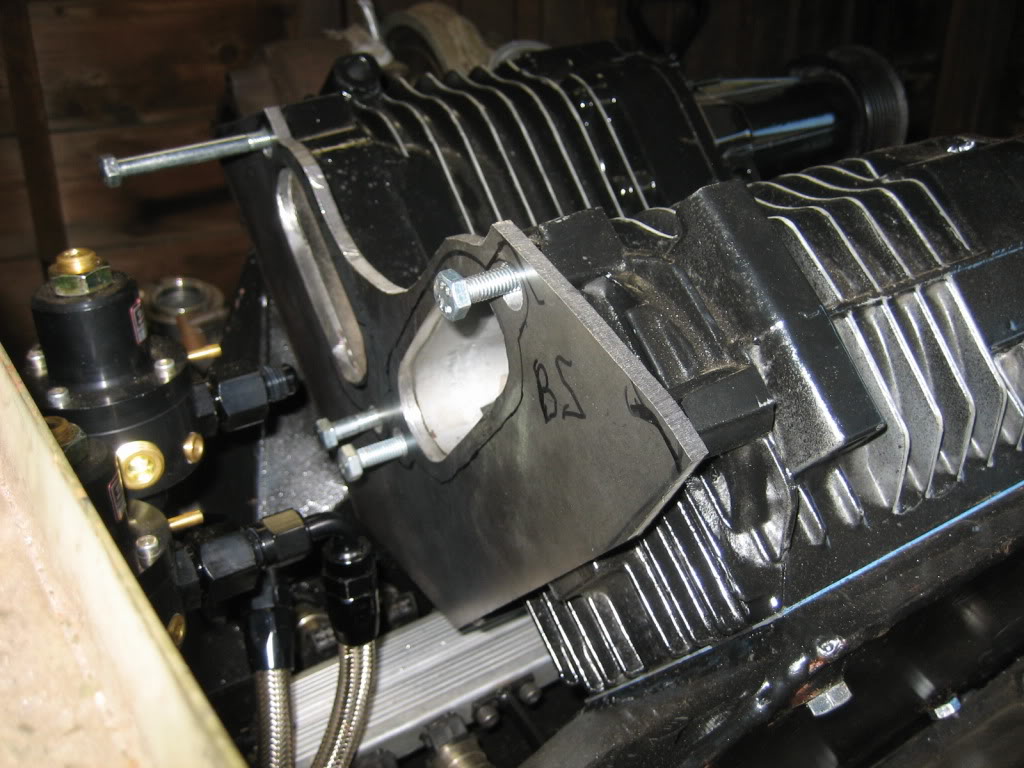
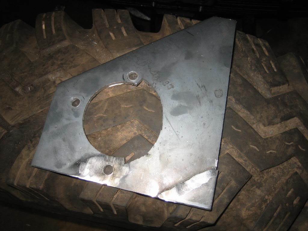
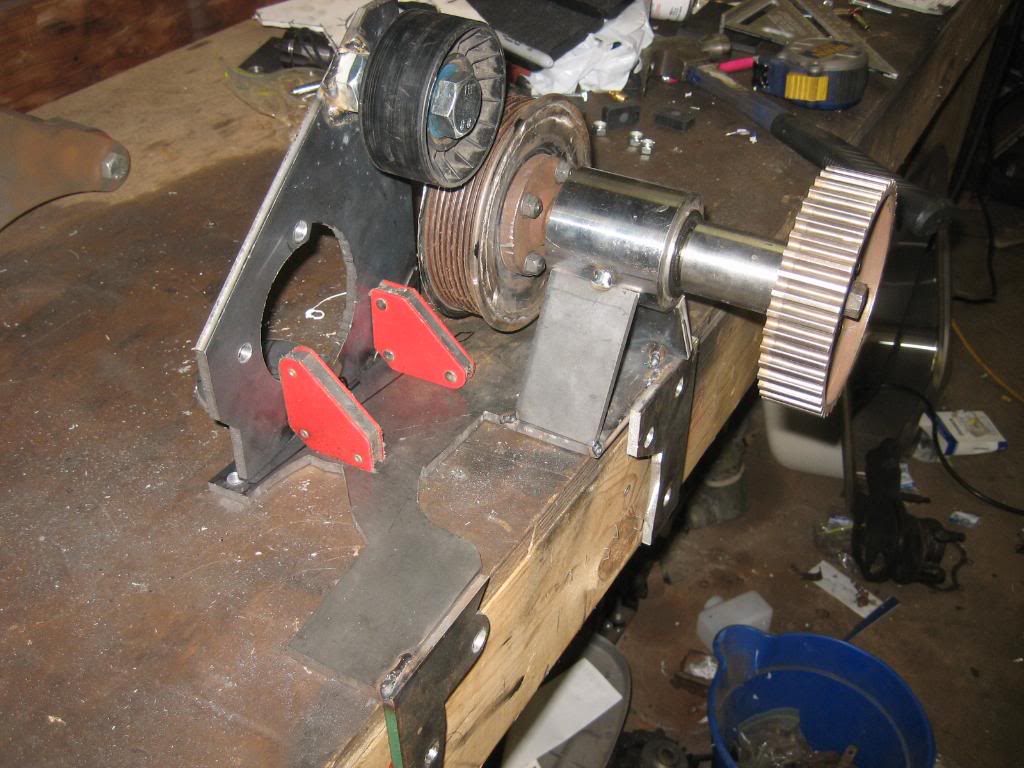
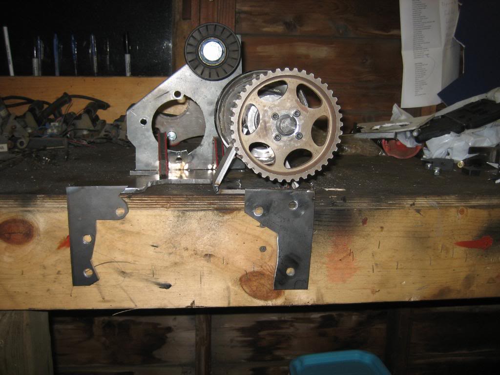
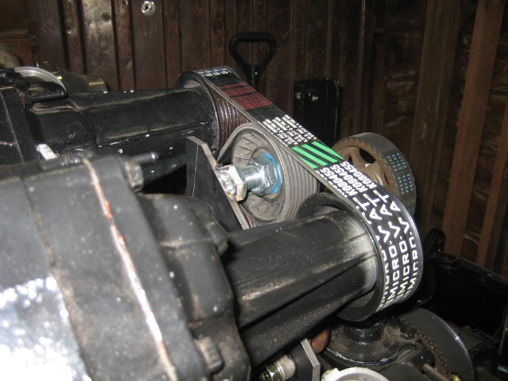
Finished the cog belt drive, and the serpentine belt is on order. The idler is on a bracket mounted to the water pump bolts and is sloted on the drivers side bolts to make tension adjustments. To tension it, you put a wrench on the bolt head in them middle of the idler, pull it tight, and then cinch the water pump bolts down. I plan on replacing the bolts with double ended hex studs, so that I can make adjustments to the belt tension without risking blowing the gasket on the water pump. Once I get the serp belt I can finish the rest of the drive. Was plesantly surprised at the cost, the belt was only 28 bucks. Also got the rear blower tie plate done. This is the plate that will weld to the the charge piping and carry the air from the turbos to the blower inlets. I need to make a front one as well that will tie the two blowers together at the front to keep them from flexing. Originally, the blowers were held down by 3 large bolts, but I could not get that system to work correctly, so they are held to the manifolds by the 4 bolts that originally held the discharge caps on, and I don't believe that they were designed to hold the blower's weight, so the plates will help tie them together and take some of the load off the 4 original bolts.
Thread Starter
1.0 BAR
Joined: Feb 2003
Posts: 461
From: Wisconsin
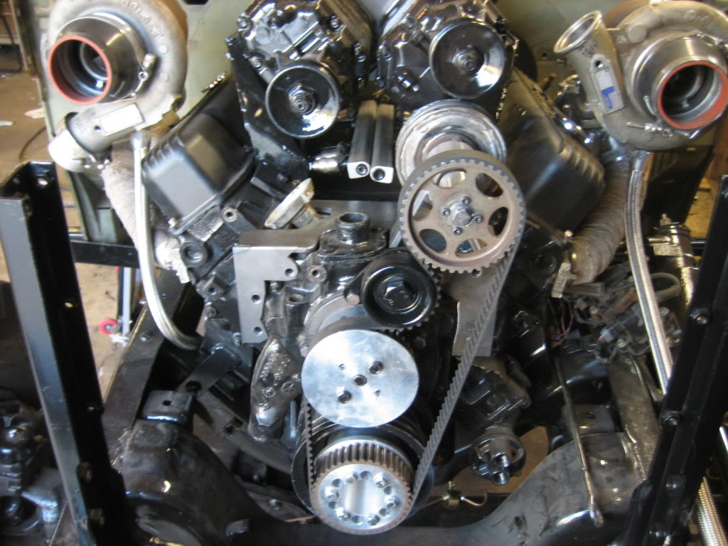
finished tacking and basic assembly of the blower drive bracket. Got the idler installed, as well as the tensioner for the serpentine belt. that thing travels all over!
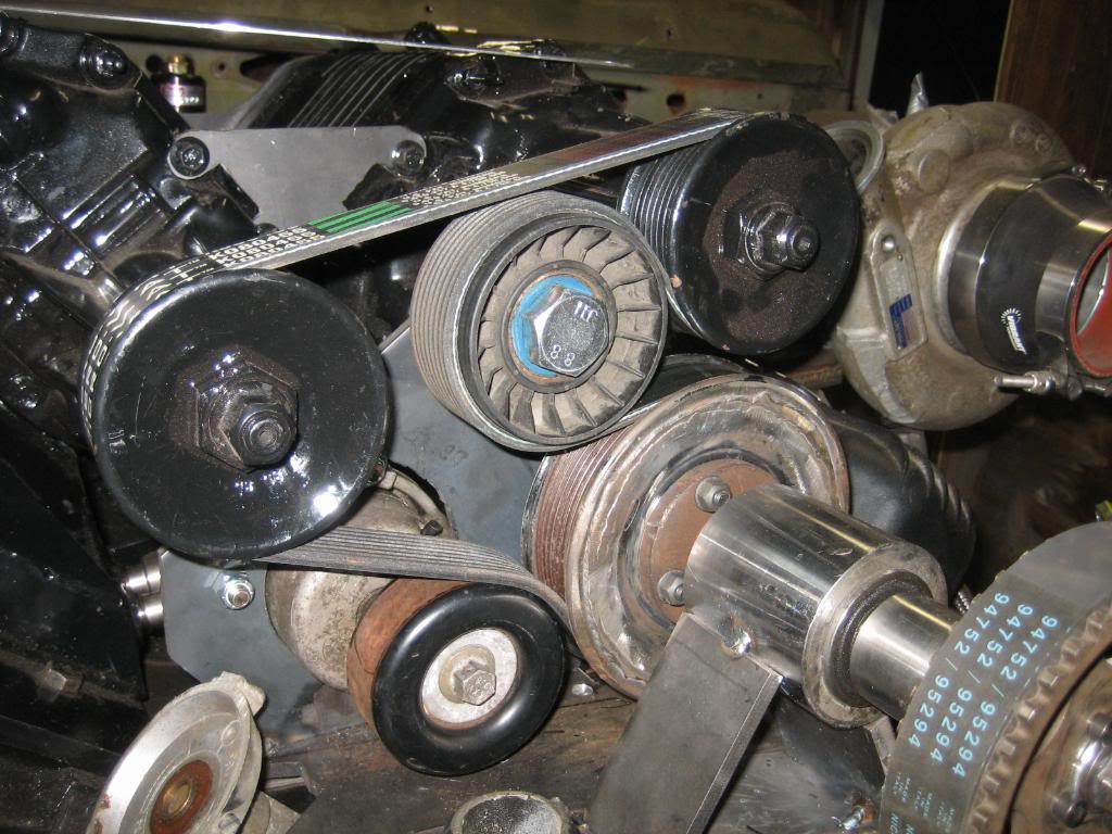
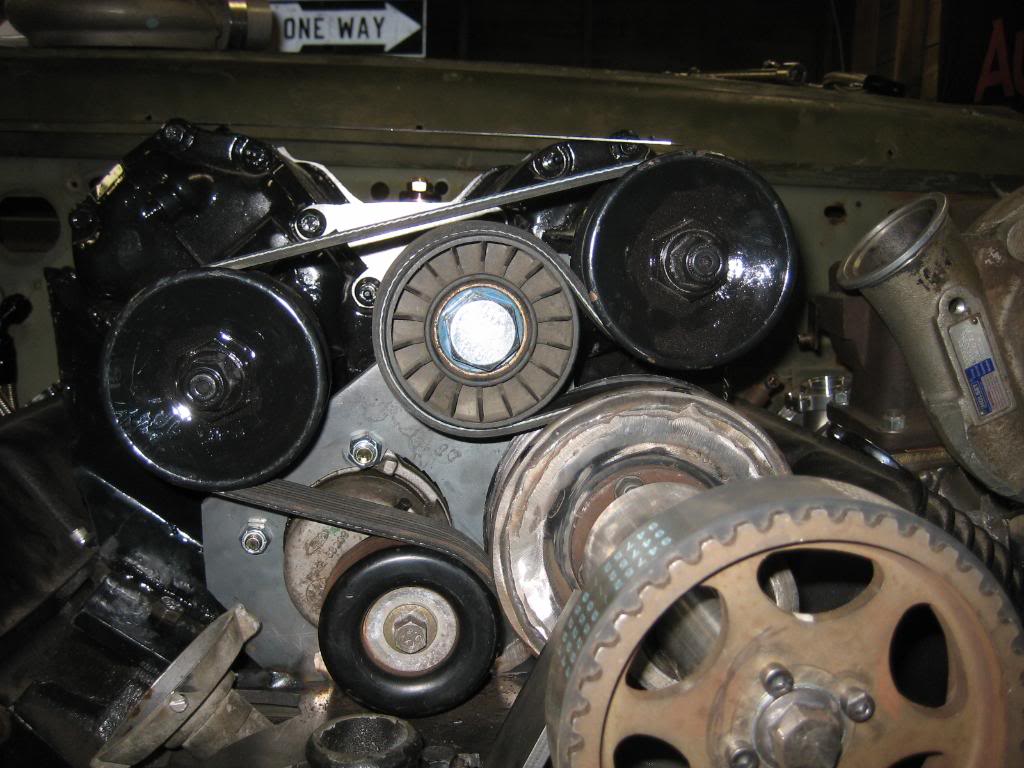
And, A video of the blowers/jackshaft being spun with the drill. WARNING: The drill makes a god aweful noise since it is right beside the camera mic. The fluttering sound in the background that sounds like helecopter blades is the blowers:

And, A video of the blowers/jackshaft being spun with the drill. WARNING: The drill makes a god aweful noise since it is right beside the camera mic. The fluttering sound in the background that sounds like helecopter blades is the blowers:
Thread Starter
1.0 BAR
Joined: Feb 2003
Posts: 461
From: Wisconsin
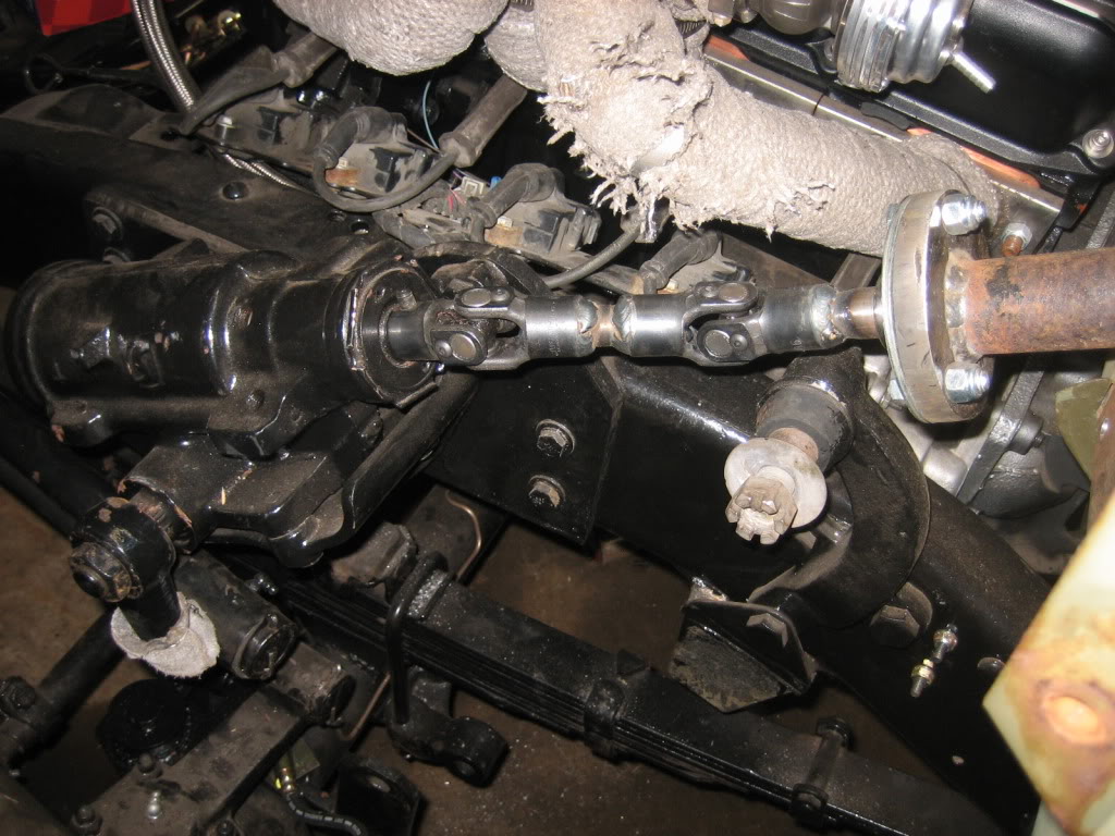
well, other than hoses, the steering system is DONE!
Finished the column tonight. got the joints welded to the shaft, and the shaft support plate welded to the column. the onyl bad thing about the way I set it up, is that with the plate on the shaft where it bolts to the firewall, it prevents you from being able to slip the U joint end on the steering box end, meaning you either have to move the cab, or take the box off its mounts. There is a little centering pin sticking out of the end of the steering box for when it had the original W200 rag joint on it, I might ty cutting that pin off and seeing if that will give me the clearance I need to be able to take the column in and out without removing the steering box. If not, it's not a big deal, as how often does the steering column need to come out for serivce anyway?
I took a few pictures, but, a video better shows the system in action, and it also shows how little slop is in the system. The best part is that it is less than 2 1/4 turns lock to lock!!!
Ignore all the noises in the video, the front left tire was banging into a piece of sheetmetal I have leaning against the garage wall. It is a compilation of clips, the first is showing number of turns, lock to lock (count 'em, less than 2 1/4!!!), second is showing the joints and column (was turning it with one hand, and holding the camera with the other, hence the slow pace), and the third is showing how little slop is in the system. The back and forth motion is to tighten it up all the way down to the steering knuckle arm... so that include the spring movement in all 4 socket joints!
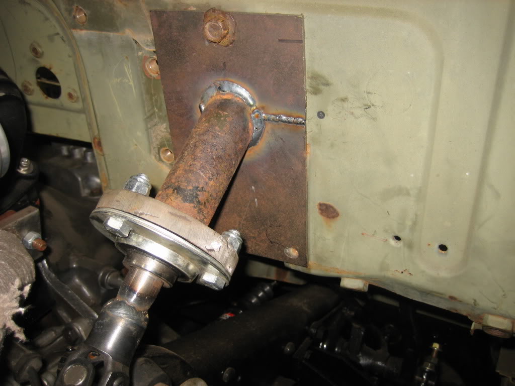
Thread Starter
1.0 BAR
Joined: Feb 2003
Posts: 461
From: Wisconsin
I made a schedule in true engineering fashion to track my progress and keep myself on track. Tenative final assembly date is second week of August. So far, I'm on track 2 weeks into the schedule I put together.
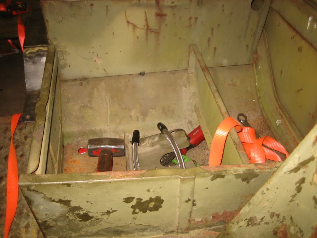
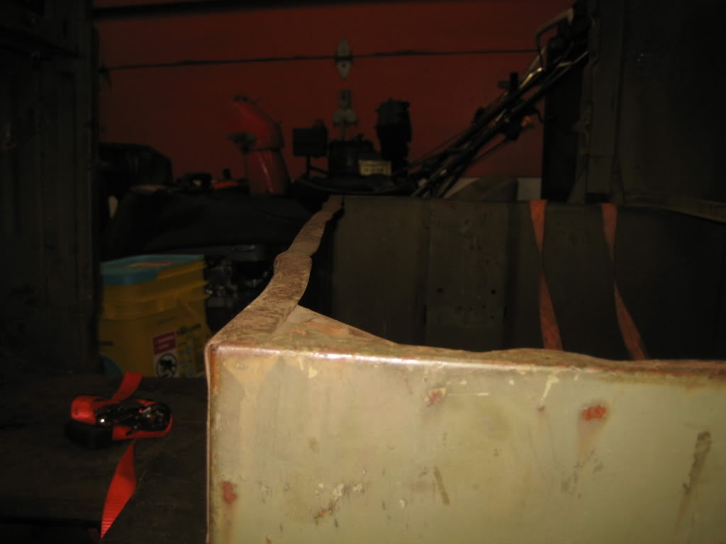
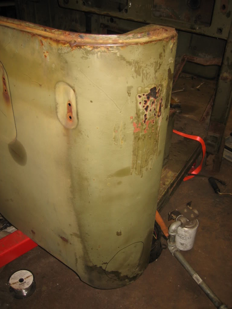
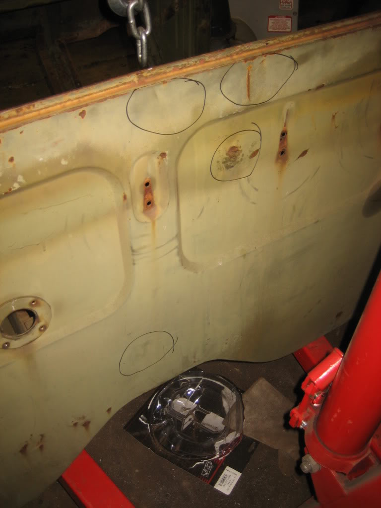
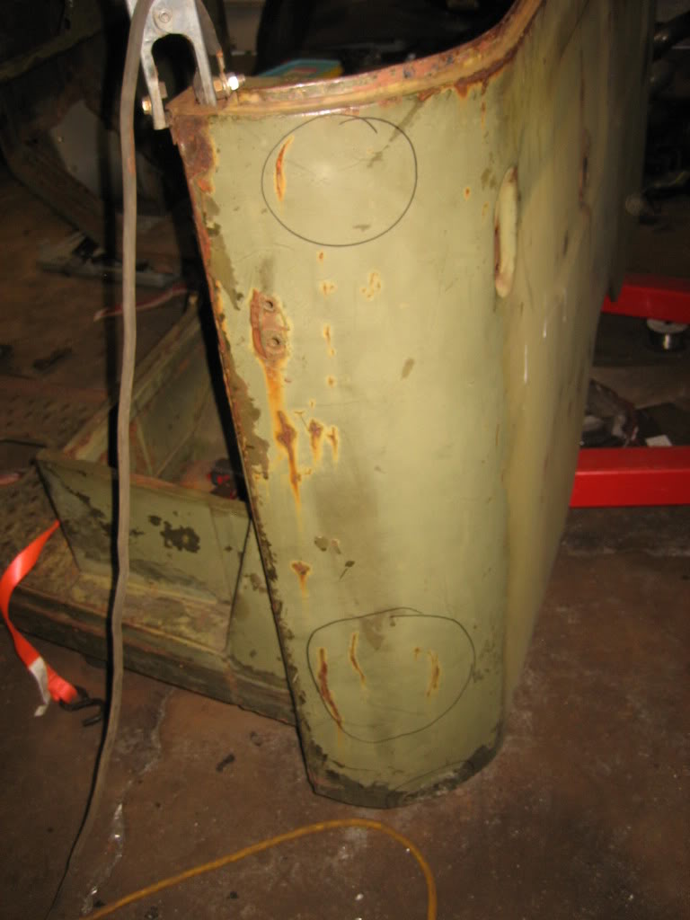
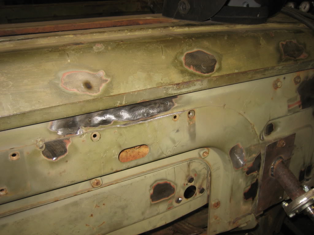
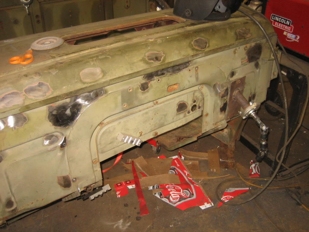
I started working on the cab tub today, banged some of the larger dents out, straightened the drip rail above the engine on the firewall, as well as straightening the box edges that the seats sit on. There are a few recessed dents left that are located on the corners where the floor is... I can't get my hammer in there to bang them back out. Was thinking of filling them with lead free metal body filler, but, does anyone else have any suggestions?
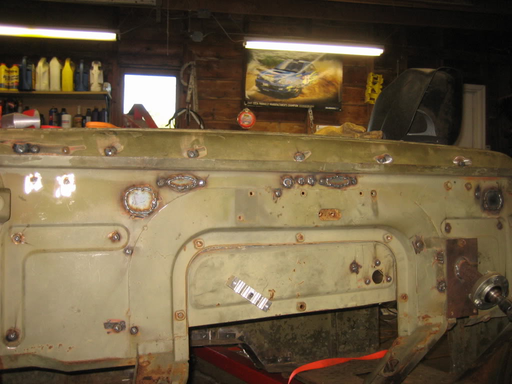
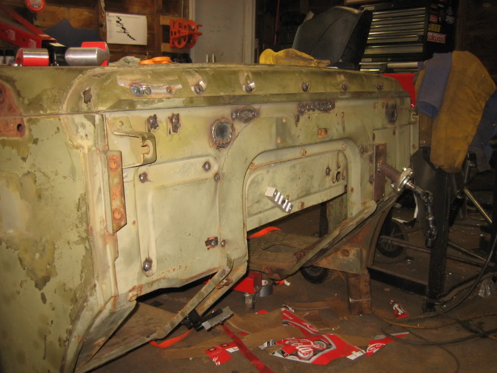
I also welded up and ground out about 80% of the holes in the firewall,just need a smidge of filler here and there. I will no longer need them, and when I had the V8 in it before, they were just a source for dirt, noise and temperature to come through. I plan on passing the wiring through the firewall in two bundles, an engine mangement bundle, and a chassis bundle. I'll use two of these to do it:
Weather Pack 22 position bulkhead connector kit DIYAutoTune.com
Then I can easily unplug the engine if it needs to come out, or the front chassis, if the front sheet metal needs to come off
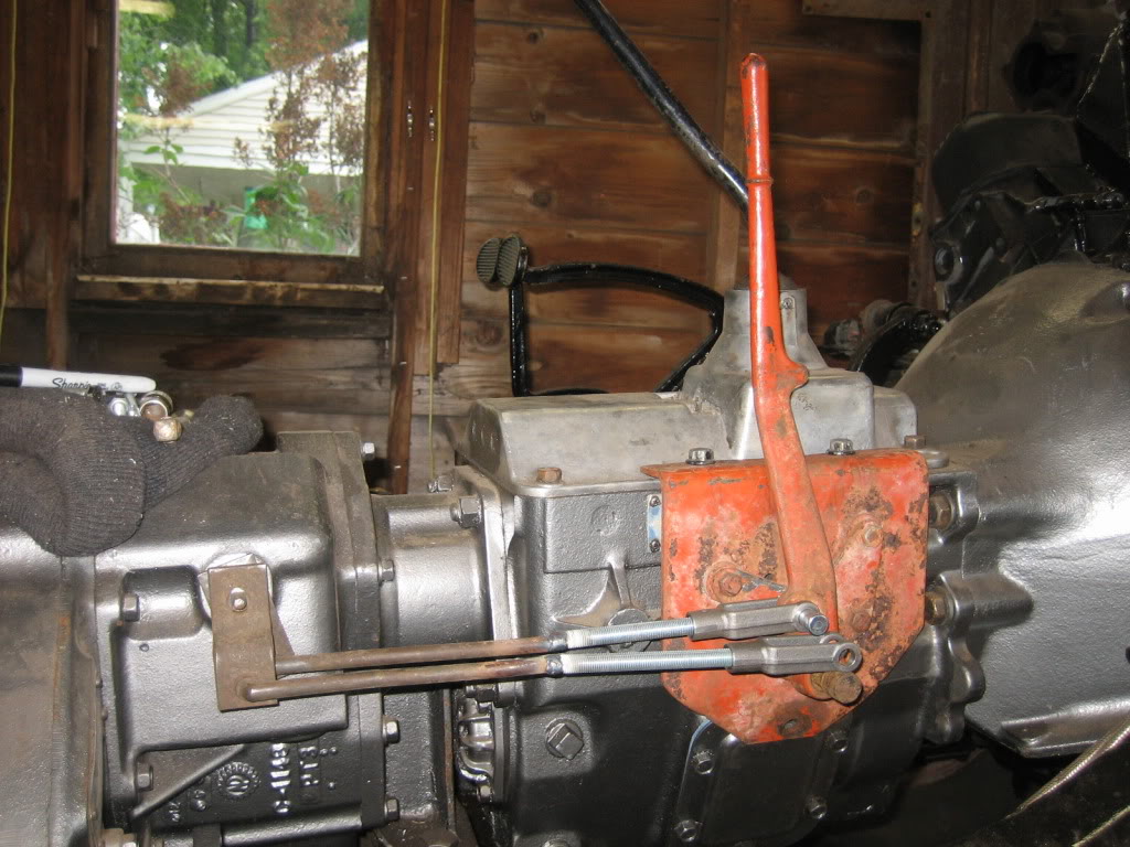
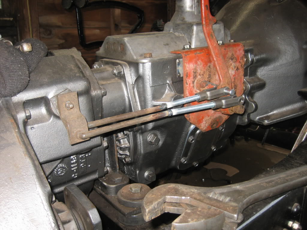
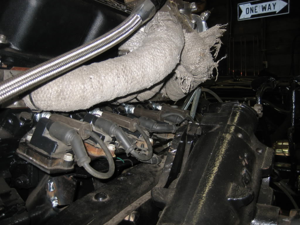
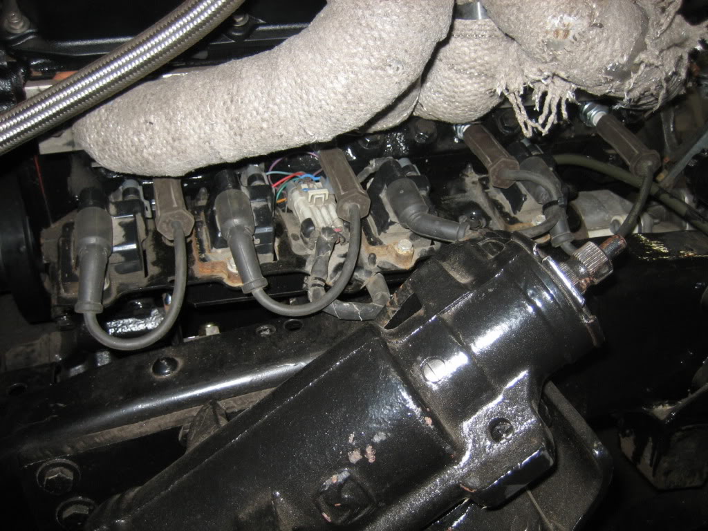
Also got the T case shift linkage mostly done. I need a second stock M37 lever, and a doghouse draft pad to go around them. I plan on mounting them side by side, instead of front to back like in the stock M. Reason being is then I can independently control the low range and the full time 4X4 lock. Also got the coilpacks mounted. Passenger's side was easy, drivers side sucked. Starter made it much harder to mount the drivers side. Also got the PS pump painted, as well as the blower drive. I need to take teh manifolds back off because I forgot to put pressure port taps in them ($^@&!^@!@ @#!@&#$! #$&$!#&!@$) but, oh well. Once those are off, I'm going to give them and the blowers a fresh coat of paint, as they have gotten pretty nicked up from all the test fitting, then they, the blower drive, the alternator, the power steering pump, and the cog belt can go on once and for all. Then, I can move on to the coolant system. I plan on making stainless steel hard lines, with just little rubber connectors on each end. This is for two reasons: 1) they look nice; and 2) the upper needs to be stiff as it passes over the jackshaft bearing so it will need to be self supporting.
Passenger's side:
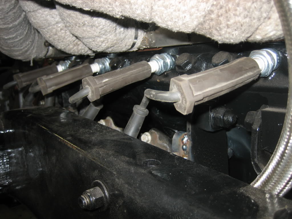
Driver's side:
I started working on the cab tub today, banged some of the larger dents out, straightened the drip rail above the engine on the firewall, as well as straightening the box edges that the seats sit on. There are a few recessed dents left that are located on the corners where the floor is... I can't get my hammer in there to bang them back out. Was thinking of filling them with lead free metal body filler, but, does anyone else have any suggestions?
I also welded up and ground out about 80% of the holes in the firewall,just need a smidge of filler here and there. I will no longer need them, and when I had the V8 in it before, they were just a source for dirt, noise and temperature to come through. I plan on passing the wiring through the firewall in two bundles, an engine mangement bundle, and a chassis bundle. I'll use two of these to do it:
Weather Pack 22 position bulkhead connector kit DIYAutoTune.com
Then I can easily unplug the engine if it needs to come out, or the front chassis, if the front sheet metal needs to come off
Also got the T case shift linkage mostly done. I need a second stock M37 lever, and a doghouse draft pad to go around them. I plan on mounting them side by side, instead of front to back like in the stock M. Reason being is then I can independently control the low range and the full time 4X4 lock. Also got the coilpacks mounted. Passenger's side was easy, drivers side sucked. Starter made it much harder to mount the drivers side. Also got the PS pump painted, as well as the blower drive. I need to take teh manifolds back off because I forgot to put pressure port taps in them ($^@&!^@!@ @#!@&#$! #$&$!#&!@$) but, oh well. Once those are off, I'm going to give them and the blowers a fresh coat of paint, as they have gotten pretty nicked up from all the test fitting, then they, the blower drive, the alternator, the power steering pump, and the cog belt can go on once and for all. Then, I can move on to the coolant system. I plan on making stainless steel hard lines, with just little rubber connectors on each end. This is for two reasons: 1) they look nice; and 2) the upper needs to be stiff as it passes over the jackshaft bearing so it will need to be self supporting.
Passenger's side:
Driver's side:

Thread Starter
1.0 BAR
Joined: Feb 2003
Posts: 461
From: Wisconsin
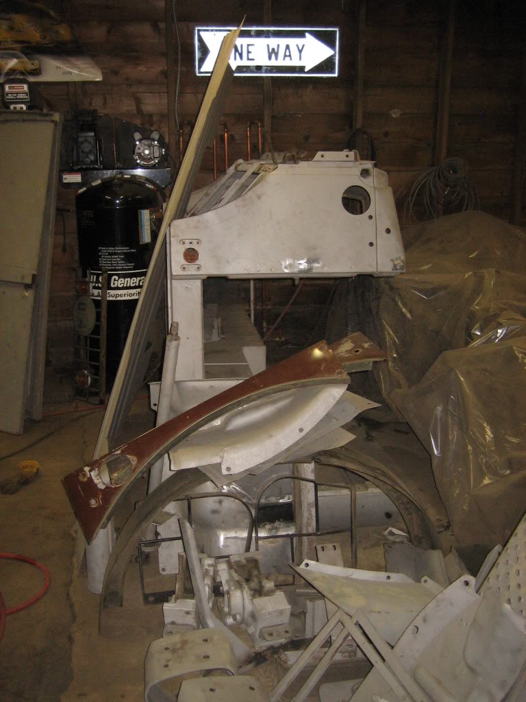
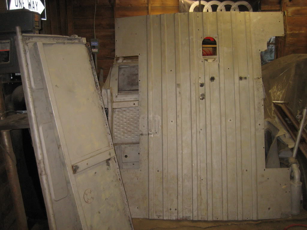
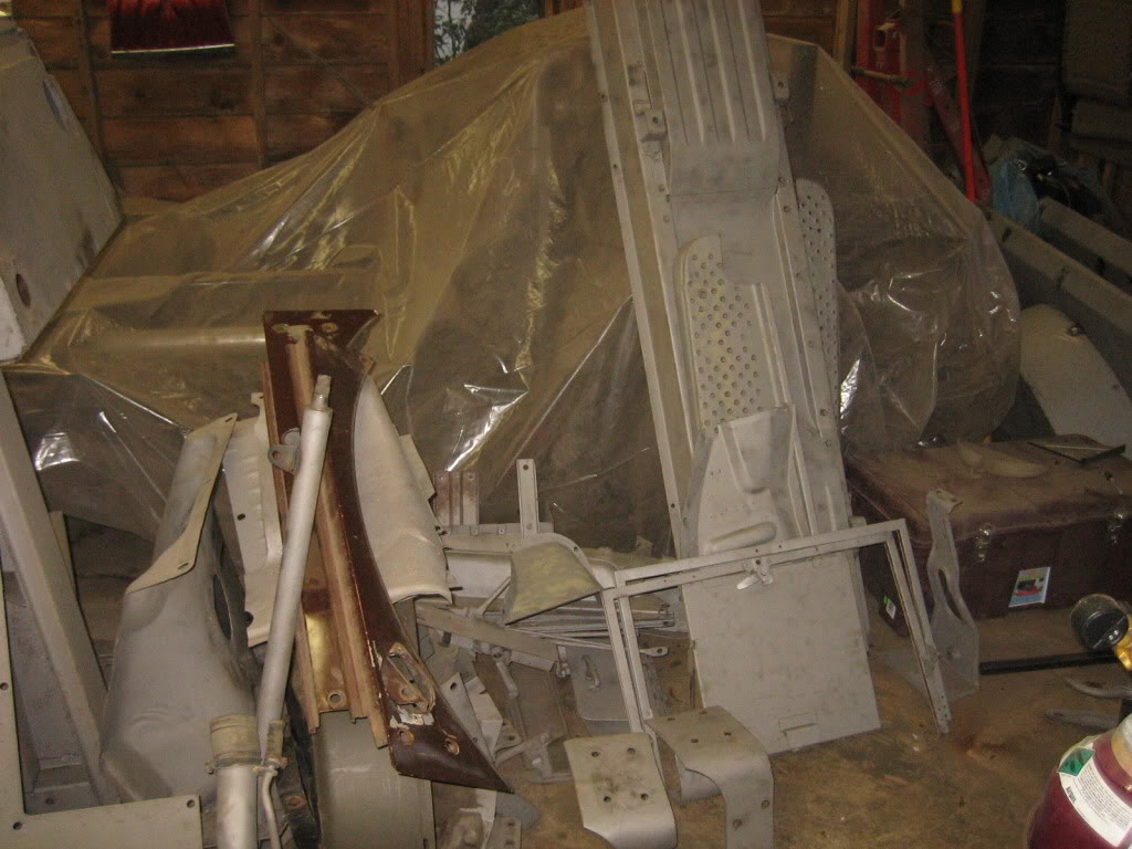
Not dead, just busy... took FIFTY SIX hours of sandblasting to strip the entire body bare. Then another 20 or so for setup and clean up, and another 40 hours or so to weld up, grind out, and straighten all the panels.
Decided on a paint color as well. The fenders, grille, running boards, and other parts will be 2006 MAzdaspeed 6 Mica Black (color of my DD), and the main tub, fenders, doors, bed, etc will be 2011 Toyota Magnetic Grey Mettalic. Very nice color combo. Picked up the paint already, it HURT. $750 for all the supplies, which, in the grand scheme of things isn't that bad, but, its a whole lot of money at one time.
Look Ma, no rust!!
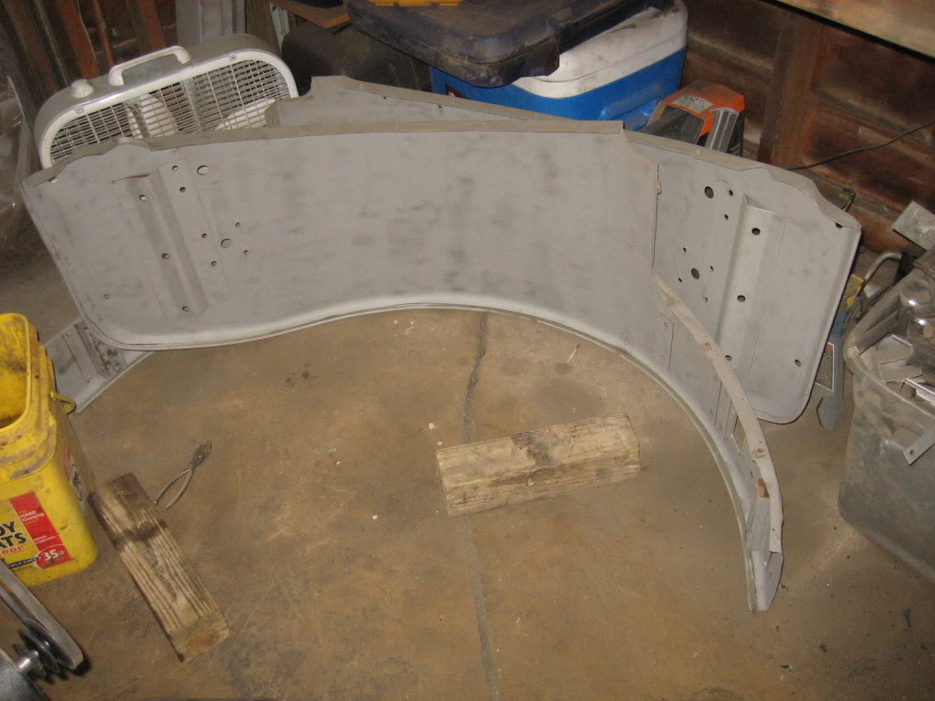
my big pile of clean, straight, rust free metal:
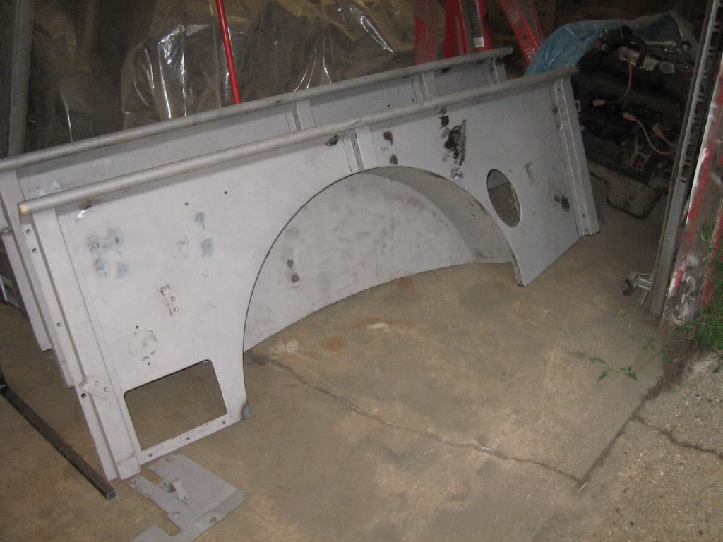
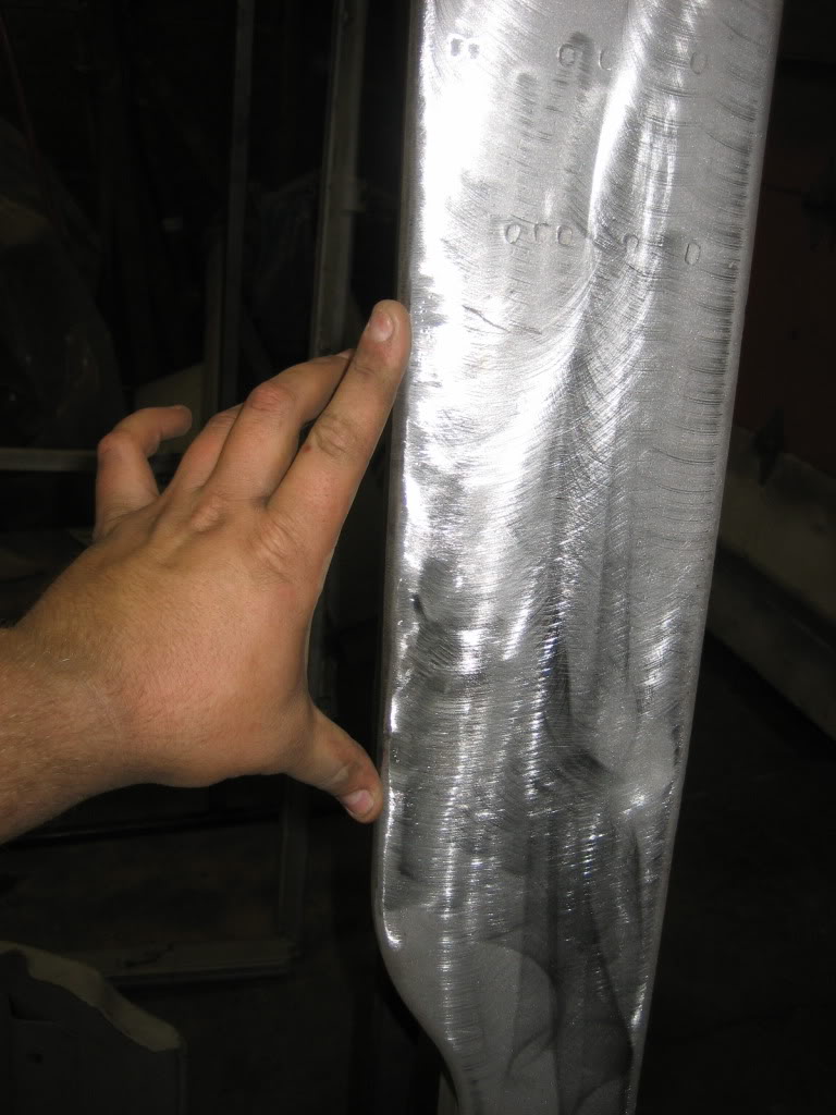
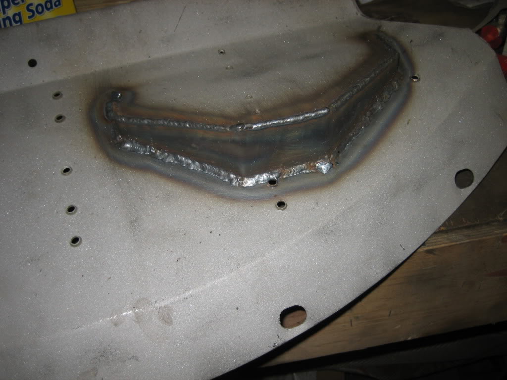
Rust in this piece from one fingertip to the other. Cut it out, welded in new:
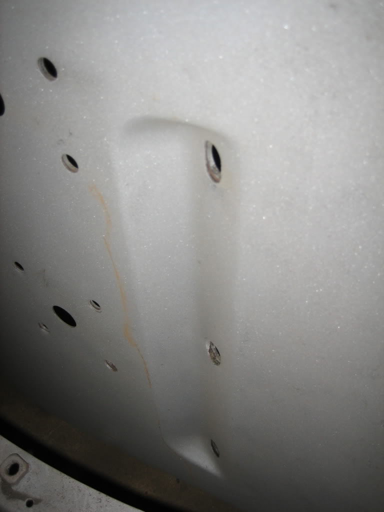
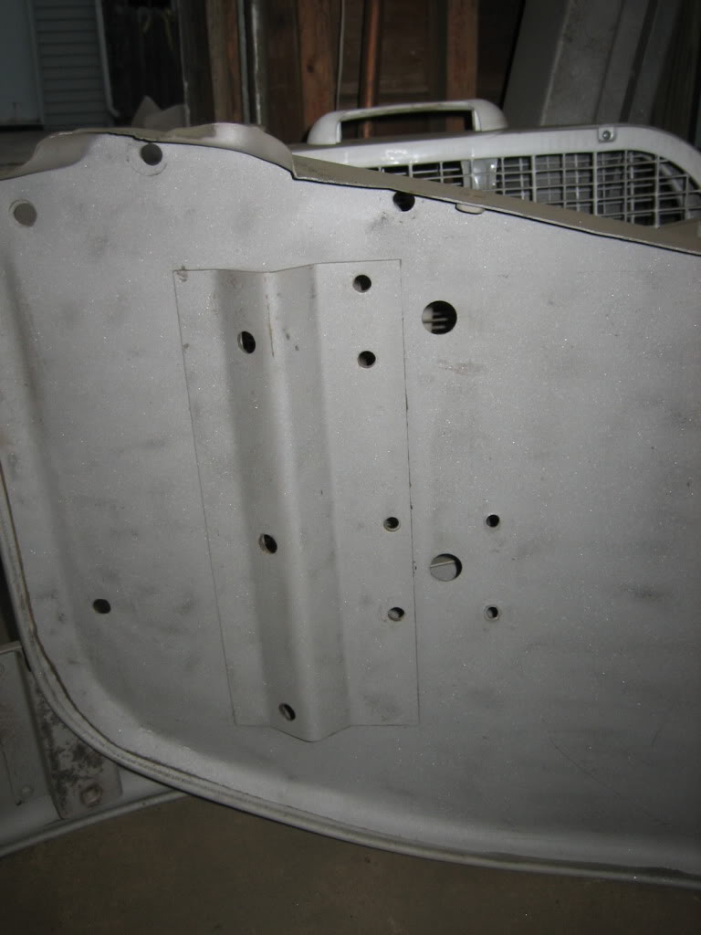
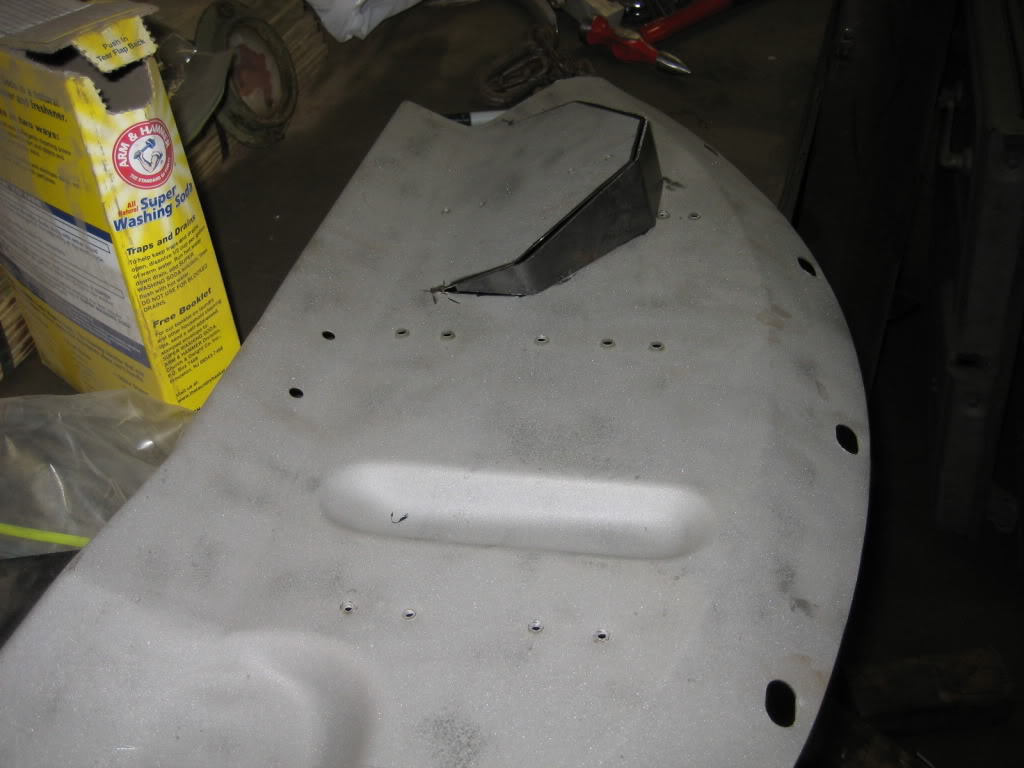
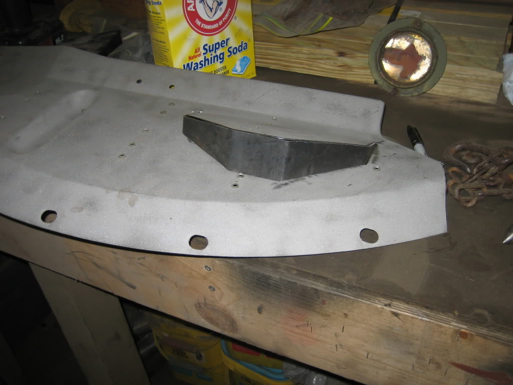
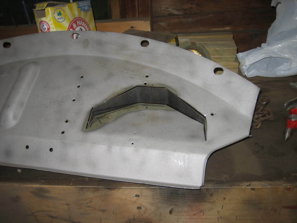
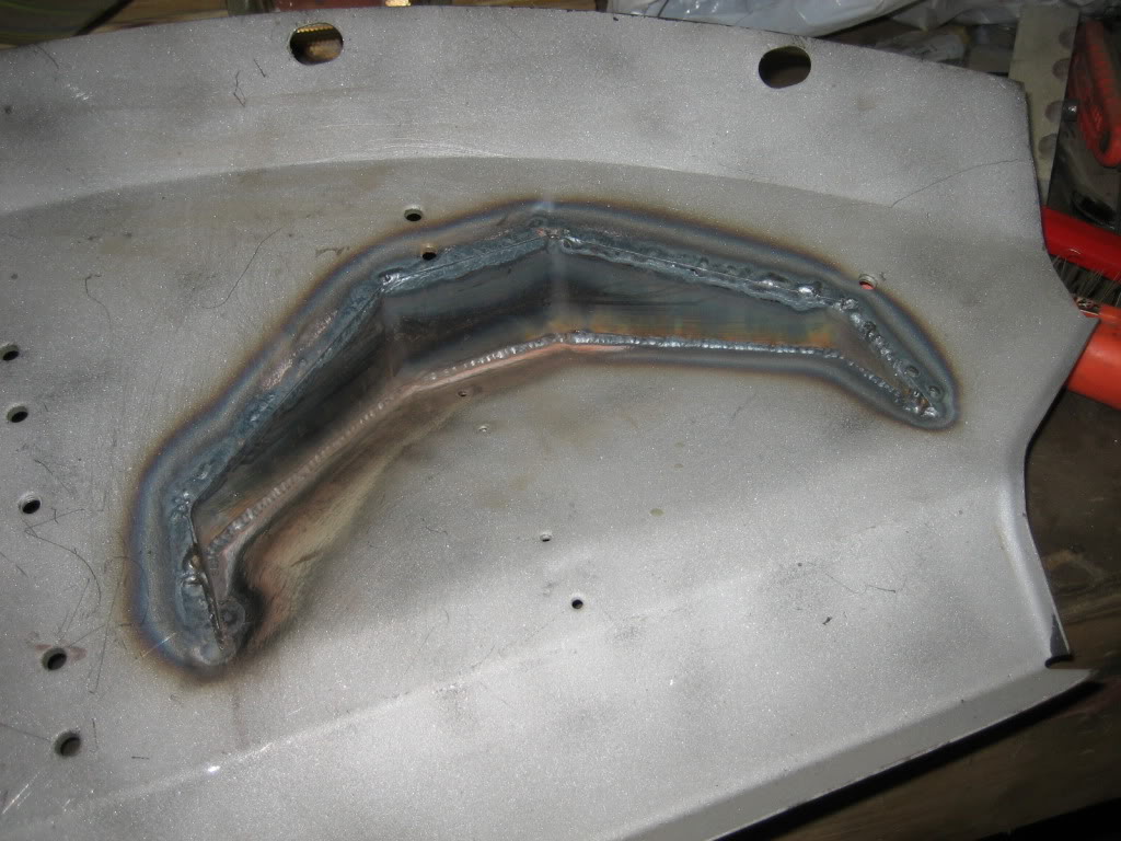
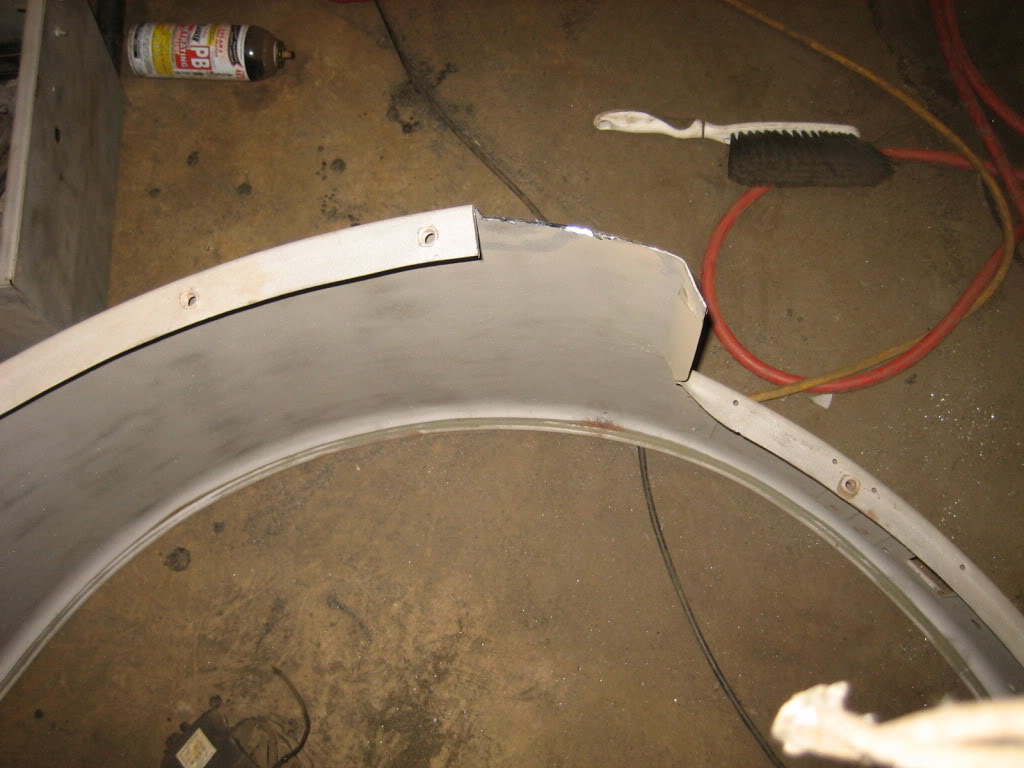
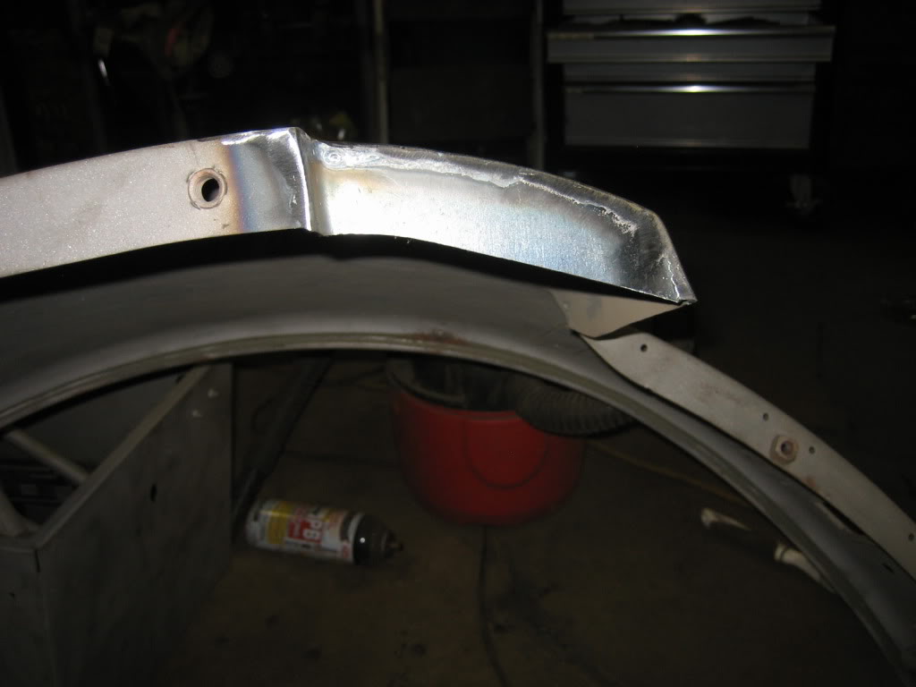
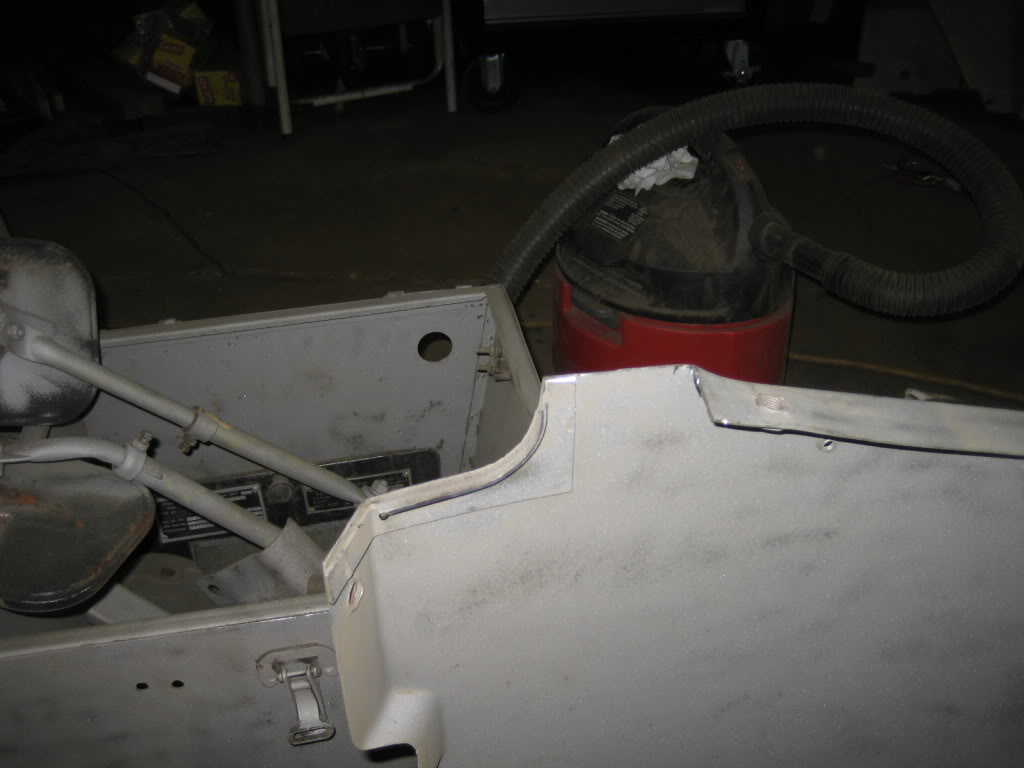
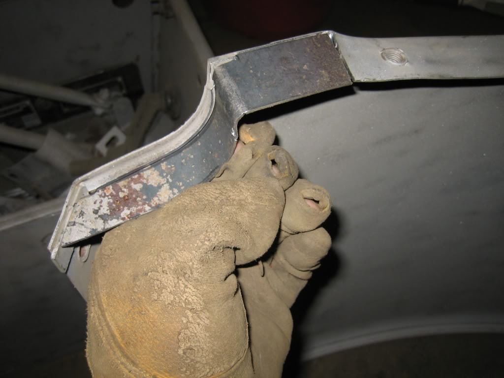
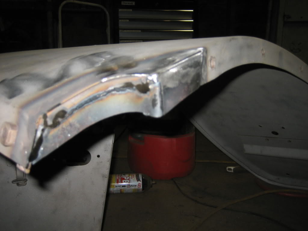
Had to modify the passenger's inner splash shield to clear the turbo header. Somewhere I made a boo-boo and it ended up hitting the header collector by about 1/2", so rather than bending the crap out of it to try and get it to clear, I made a bump out:
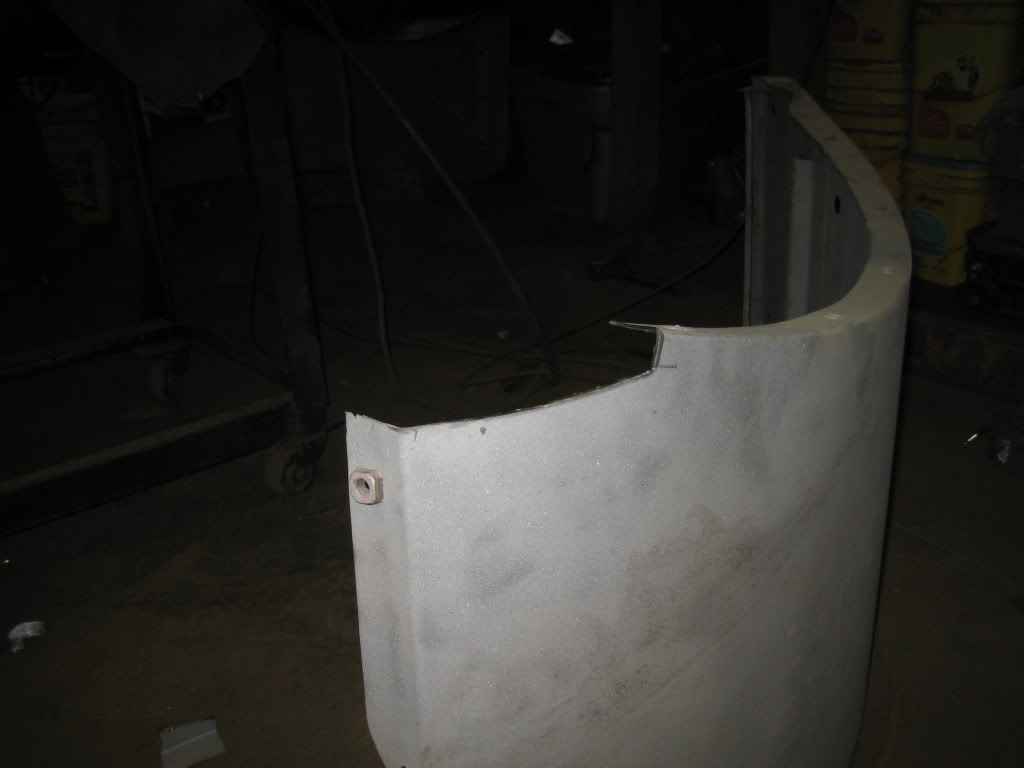
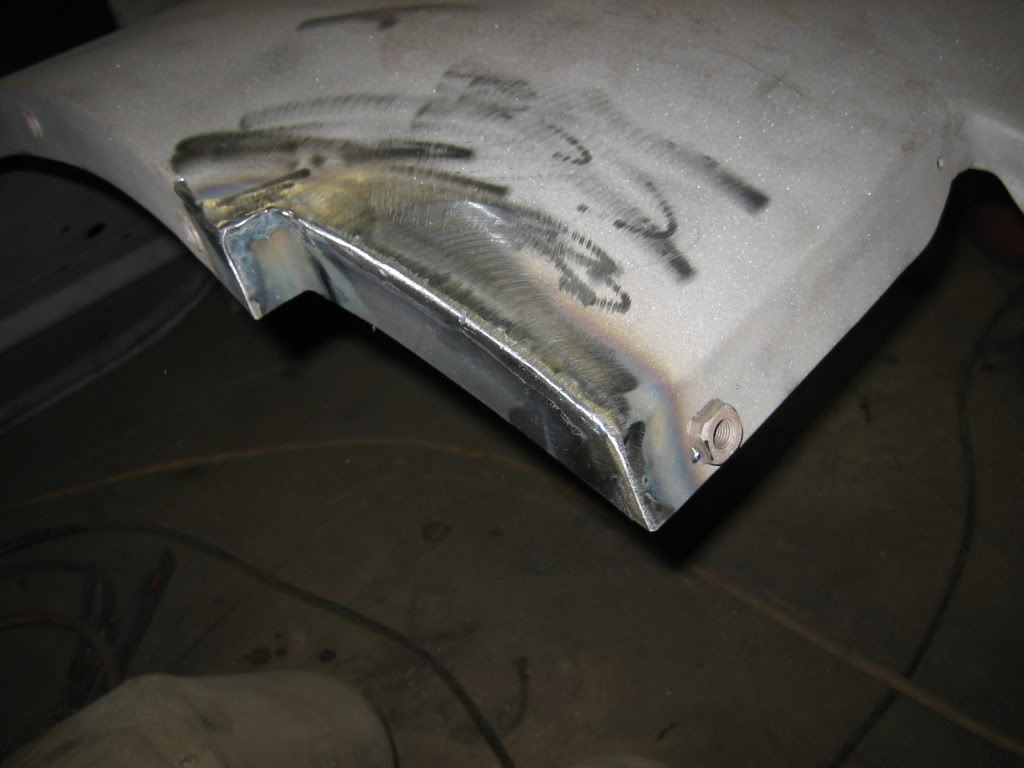
Also had to trim both front fenders to get the down pipes to fit, so, I welded in a lip where i had trimmed it to prevent the fenders from flexing and cracking:
Passenger's side
Driver's side:
Decided on a paint color as well. The fenders, grille, running boards, and other parts will be 2006 MAzdaspeed 6 Mica Black (color of my DD), and the main tub, fenders, doors, bed, etc will be 2011 Toyota Magnetic Grey Mettalic. Very nice color combo. Picked up the paint already, it HURT. $750 for all the supplies, which, in the grand scheme of things isn't that bad, but, its a whole lot of money at one time.
Look Ma, no rust!!
my big pile of clean, straight, rust free metal:
Rust in this piece from one fingertip to the other. Cut it out, welded in new:
Had to modify the passenger's inner splash shield to clear the turbo header. Somewhere I made a boo-boo and it ended up hitting the header collector by about 1/2", so rather than bending the crap out of it to try and get it to clear, I made a bump out:
Also had to trim both front fenders to get the down pipes to fit, so, I welded in a lip where i had trimmed it to prevent the fenders from flexing and cracking:
Passenger's side
Driver's side:
Last edited by josh19wrc; Jul 14, 2010 at 10:53 PM.
Thread Starter
1.0 BAR
Joined: Feb 2003
Posts: 461
From: Wisconsin
More work done, all parts are in primer, of some variety! Almost ready to shoot the fenders, grille, and running boards in black.
Took out a loan for 4K, should be just enough to finish. Didn't really want to, but, also dont want the build to stretch out into next summer, it needs to be done this summer. Once they put the cash in my checking account, I'm going on a spending spree!
Filled the brakes and clutch with fluid, bled them, and they work flawlessly, no issues at all. My clutch calculations were spot on, just right on travel, with good feel, and not too heavy, especially considering the clutch set I picked out is rated to 800 ft-lb of torque!
Will take the rear shaft up to MSI in Green Bay tomorrow, get that cut down to 37" long, both axles are done, T case is done, need to finish the T case linkage on the side of the trans, then I can fill it with fluid, and all the drivetrain from the bellhousing back will be set. Just need to order some parts for the engine, and I can final assemble that, and light it. Give me a month-month and a half, and it will be done. :shock:
Took out a loan for 4K, should be just enough to finish. Didn't really want to, but, also dont want the build to stretch out into next summer, it needs to be done this summer. Once they put the cash in my checking account, I'm going on a spending spree!
Filled the brakes and clutch with fluid, bled them, and they work flawlessly, no issues at all. My clutch calculations were spot on, just right on travel, with good feel, and not too heavy, especially considering the clutch set I picked out is rated to 800 ft-lb of torque!
Will take the rear shaft up to MSI in Green Bay tomorrow, get that cut down to 37" long, both axles are done, T case is done, need to finish the T case linkage on the side of the trans, then I can fill it with fluid, and all the drivetrain from the bellhousing back will be set. Just need to order some parts for the engine, and I can final assemble that, and light it. Give me a month-month and a half, and it will be done.
:shock:


