
Power Wagon Rebuild (Update: 11/5/08)


Thread Starter
1.0 BAR
Joined: Feb 2003
Posts: 461
From: Wisconsin
turbos will draw in through a common aircleaner/snorkel, then blow through a 2into 1 air to water intercooler, then into the supercharger. The S/C will blow into a air to water intercooler, then into the carb, with BOV's on both the common pipe from the turbos and after the S/C'r.
Thread Starter
1.0 BAR
Joined: Feb 2003
Posts: 461
From: Wisconsin
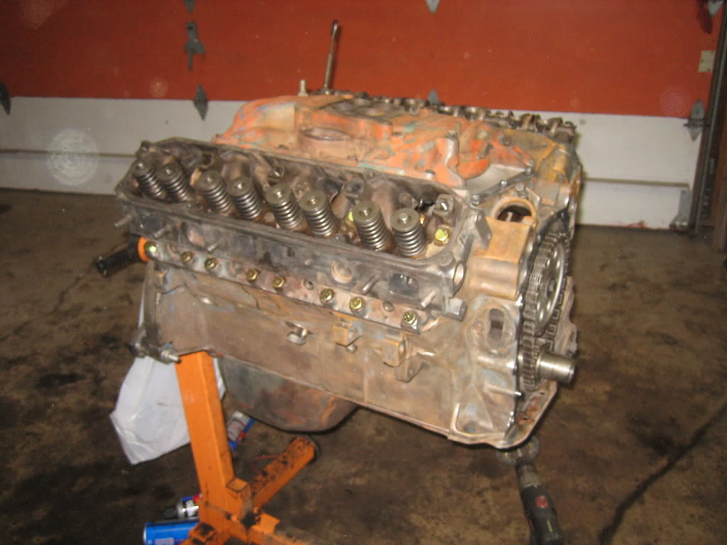
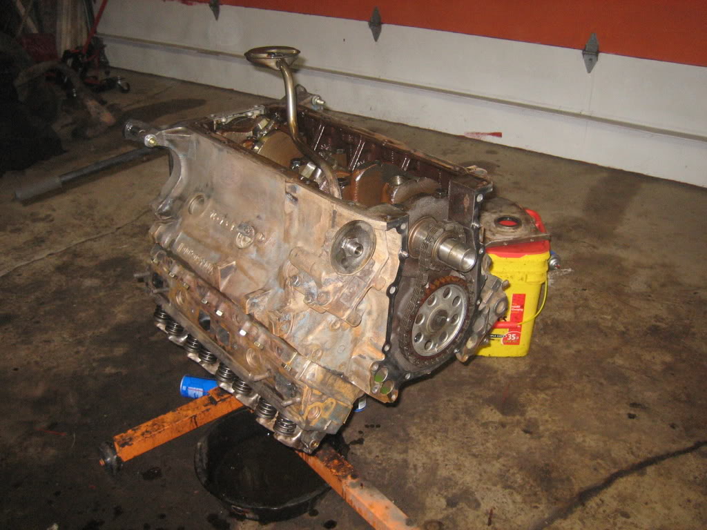
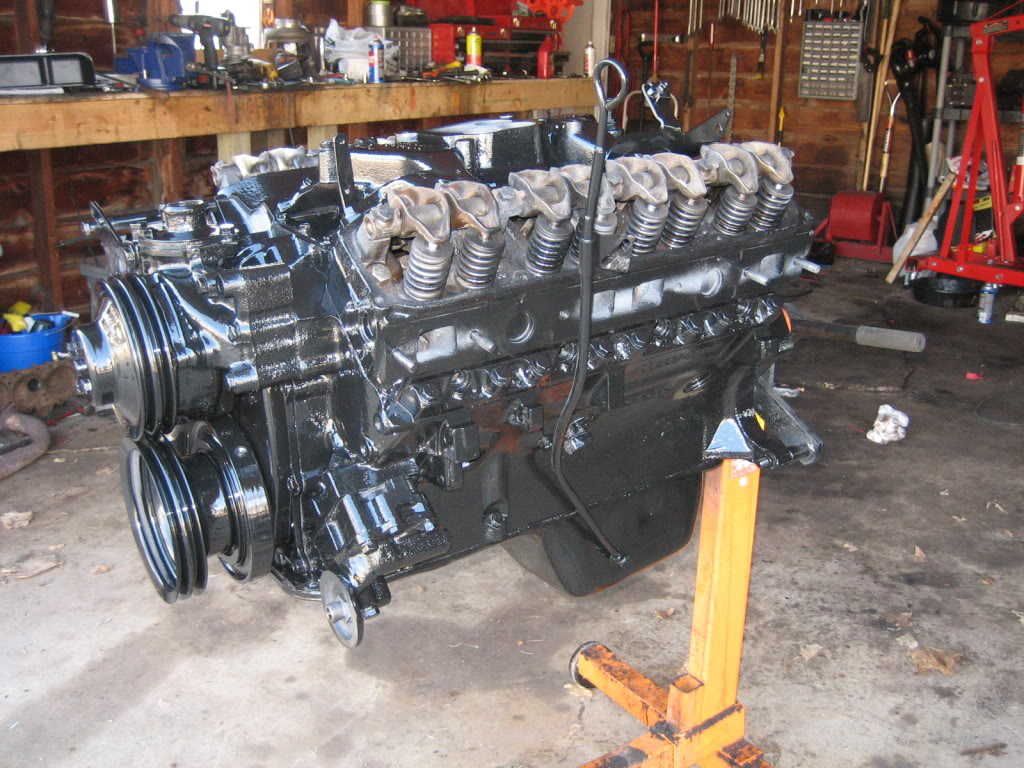
more work done tonight:
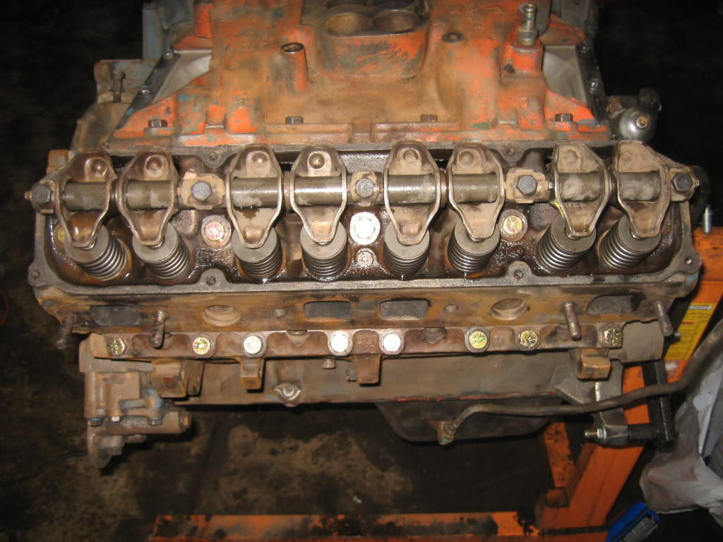
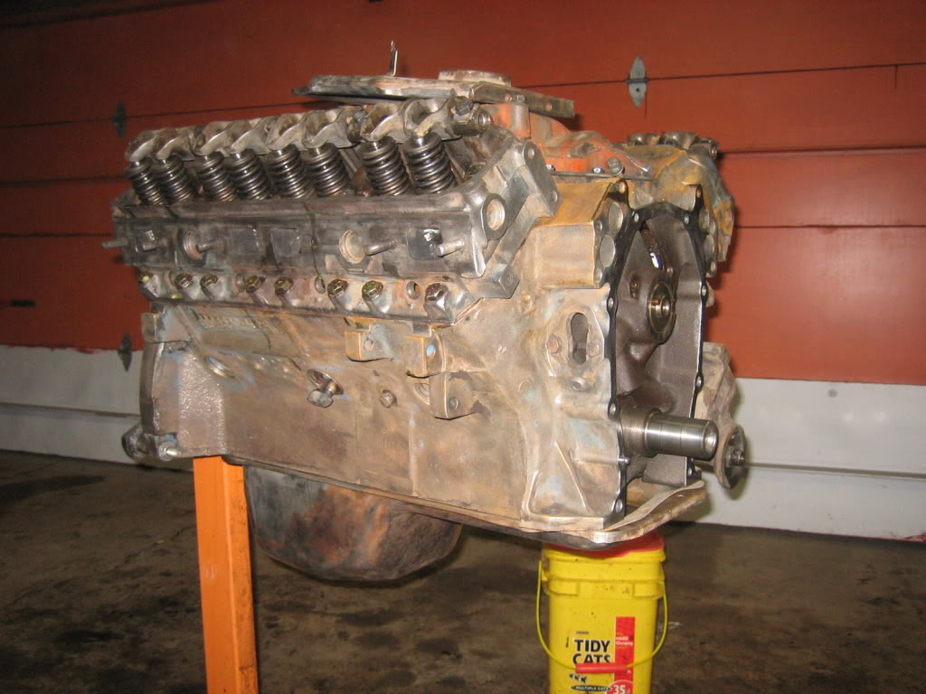
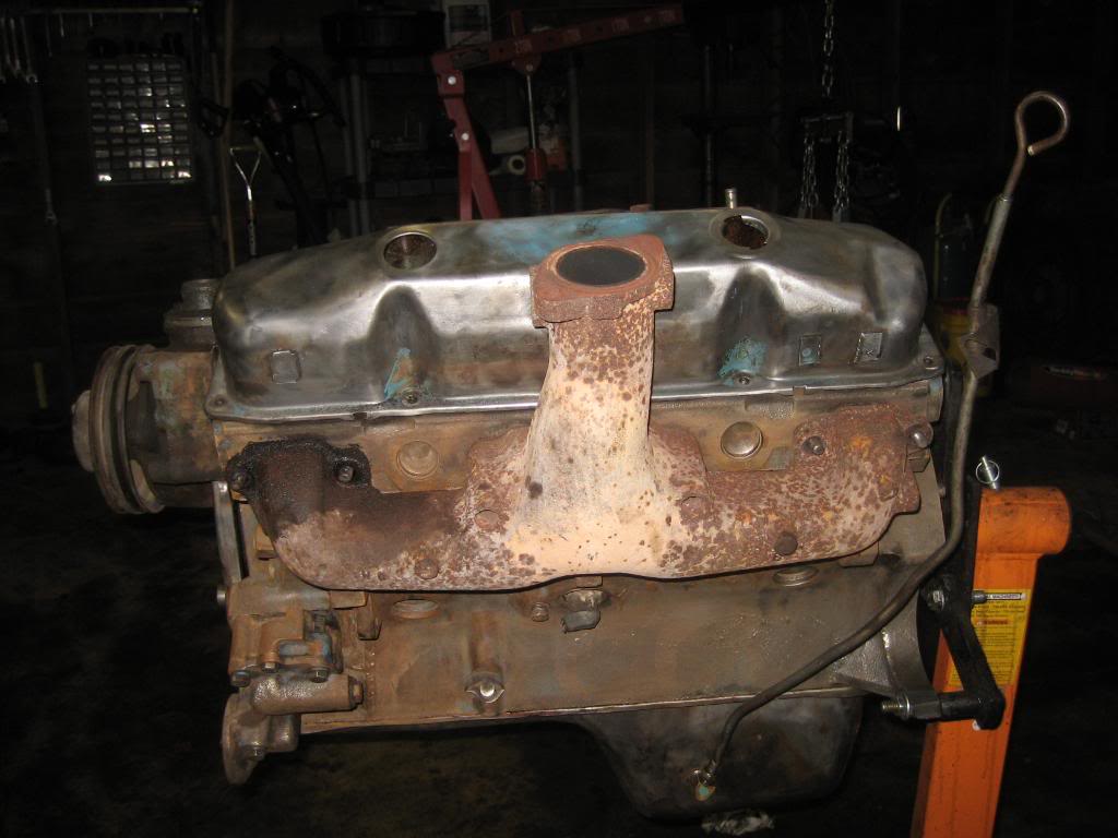
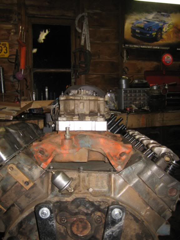
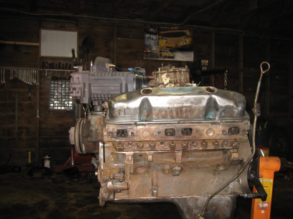
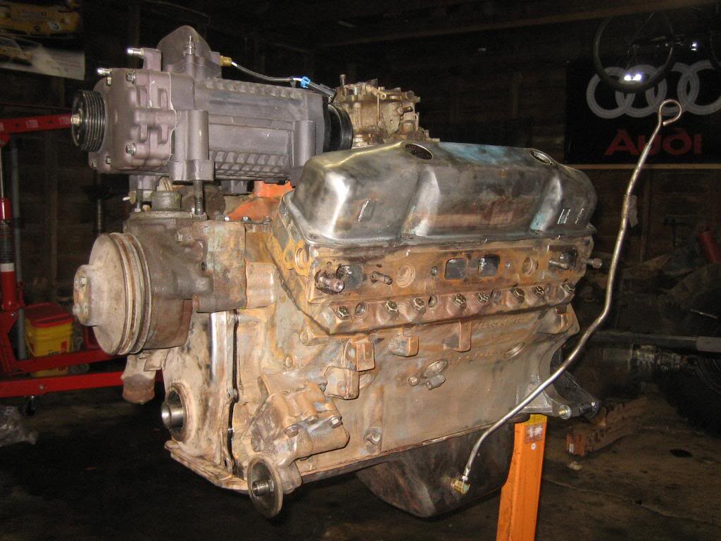
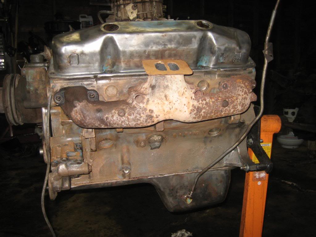
Got the second head finished, and put back on. My dad brought down a spare head and I pulled a few matching OEM valves out of it, lapped them in, and put it back on.
Wasn't comfortable with the mish-mash of hardware that was holding them on before so I went and got some new grade 8 bolts to hold em down with. Also got the intake cleaned and put back on.
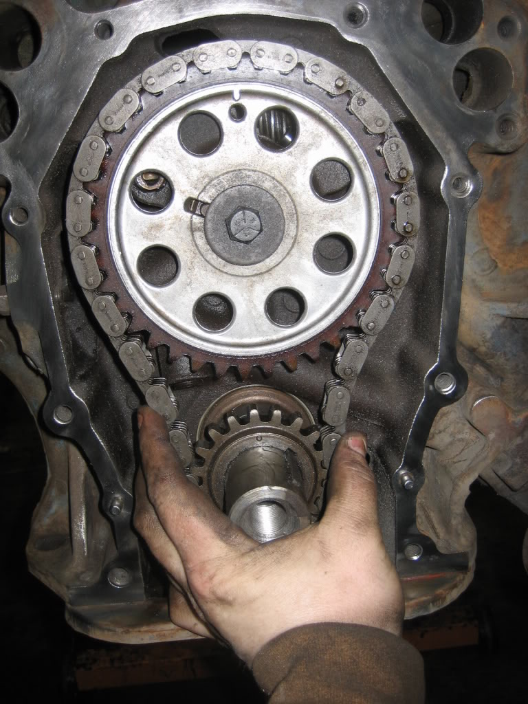
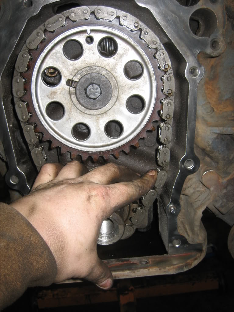
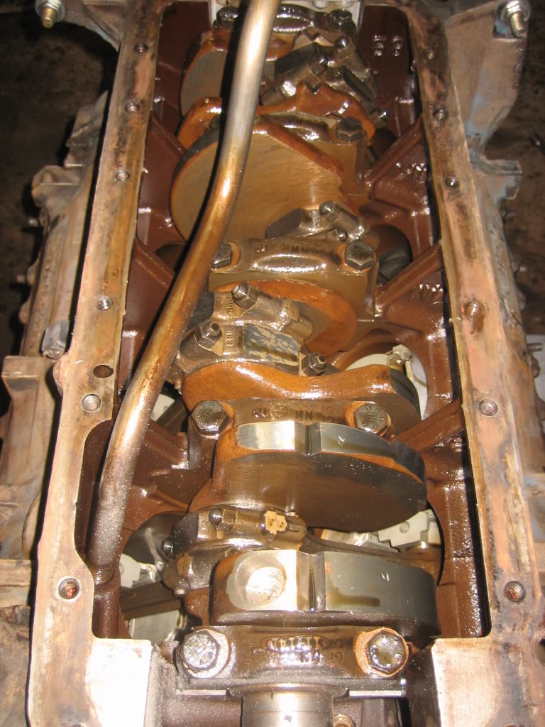
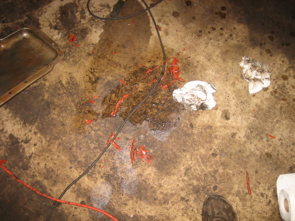
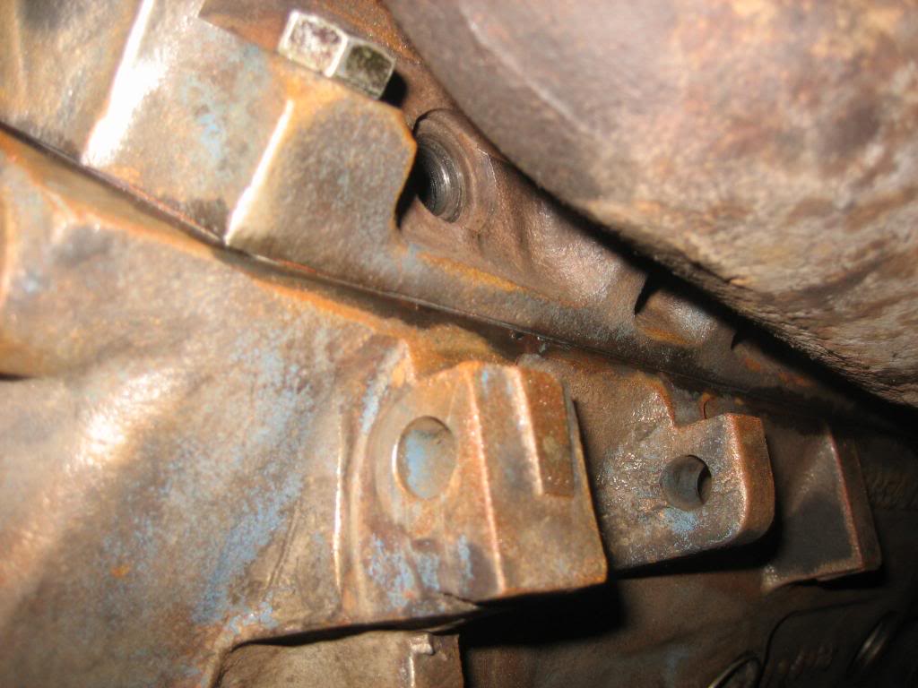
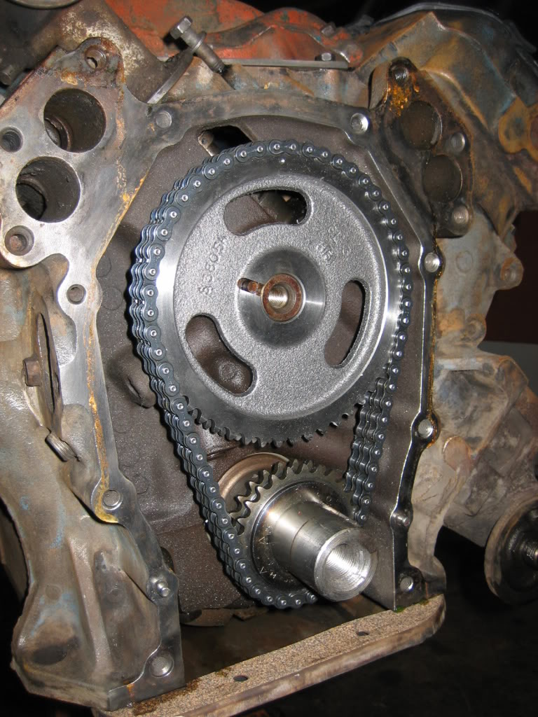
Pulled the timing cover... wasnt going to, but, I'm glad I did, as you can see the timing set is tired... another thing to order. I also popped the pan and put a proper gasket on it... the pile of red RTV in the one pic was what was holding it on...
Bad news on the supercharger front... going to have to create my own pulleys, as the 400 has a differnt bolt patters and back spacing from the block than a 360, so 360 serpentine pulleys wont work. I'm going to get it back together, and then take some measurements. I think I have an idea on how to make it work, and do it cheaply.

Got the second head finished, and put back on. My dad brought down a spare head and I pulled a few matching OEM valves out of it, lapped them in, and put it back on.
Wasn't comfortable with the mish-mash of hardware that was holding them on before so I went and got some new grade 8 bolts to hold em down with. Also got the intake cleaned and put back on.
Pulled the timing cover... wasnt going to, but, I'm glad I did, as you can see the timing set is tired... another thing to order. I also popped the pan and put a proper gasket on it... the pile of red RTV in the one pic was what was holding it on...
Bad news on the supercharger front... going to have to create my own pulleys, as the 400 has a differnt bolt patters and back spacing from the block than a 360, so 360 serpentine pulleys wont work. I'm going to get it back together, and then take some measurements. I think I have an idea on how to make it work, and do it cheaply.
Thread Starter
1.0 BAR
Joined: Feb 2003
Posts: 461
From: Wisconsin
No real serious work done tonight, just some brainstorming and fit up testing... Have some interesting results, thats for sure!
I ended up ordering my Mopar Performance cast valve covers, as well as a nice Comp Cams double roller timing set. I also ordered a fuel pmp block off plate, and the accessory kit for the valve covers.
Anyway, on to the good stuff tonight...
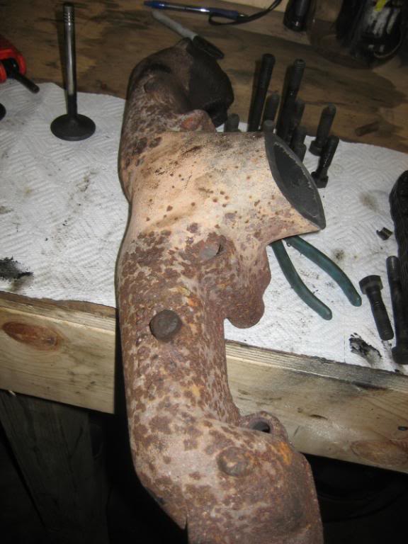
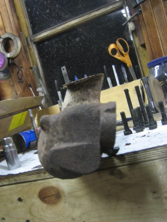
Was looking at the factory manifolds... and something occured to me...
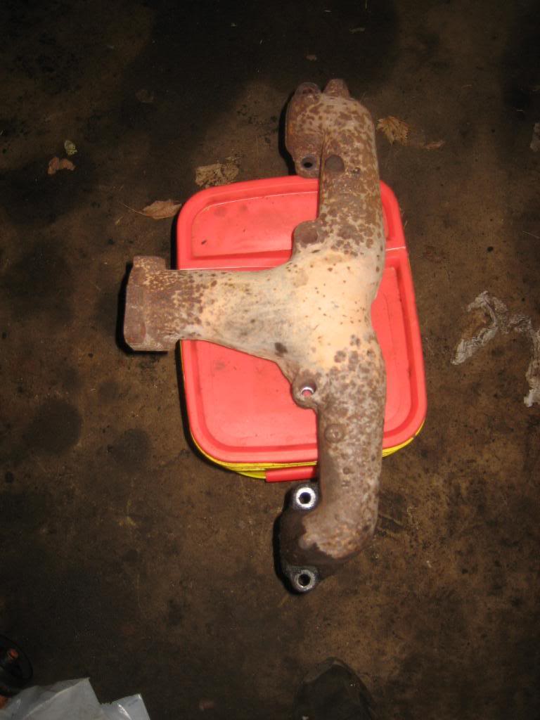
the only issue is that I can't get to the spark plug holes...
However, if I make spacer blocks 2" thick, I can get in to the plugs no problem. The total width of the engine with the spacer blocks, outside of one manifold, to outside of the other will be 30"... same as the frame, and pretty close to what my 360 measured with it's goofy mounts that I made. Near as I can tell, using the stock 1977 cross member will mount it approximately 1-2" lower in the frame, which will be perfect... The plugs will be almost laying on top of the frame.
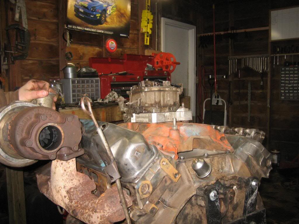
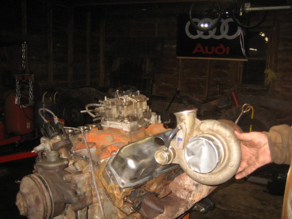
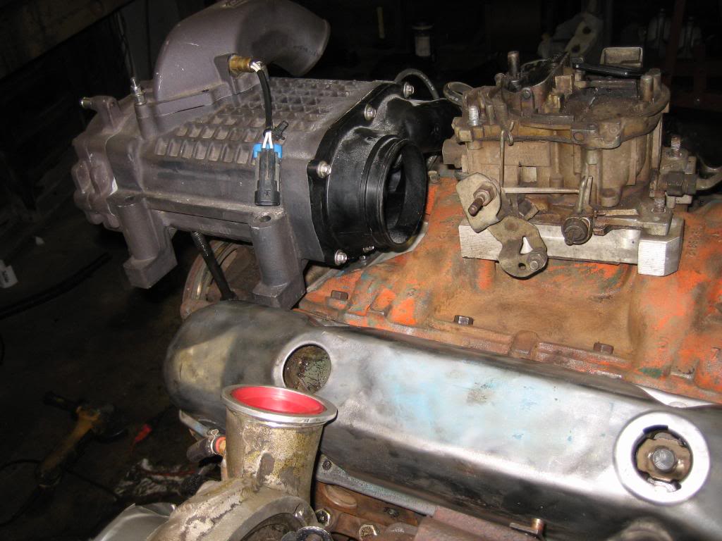
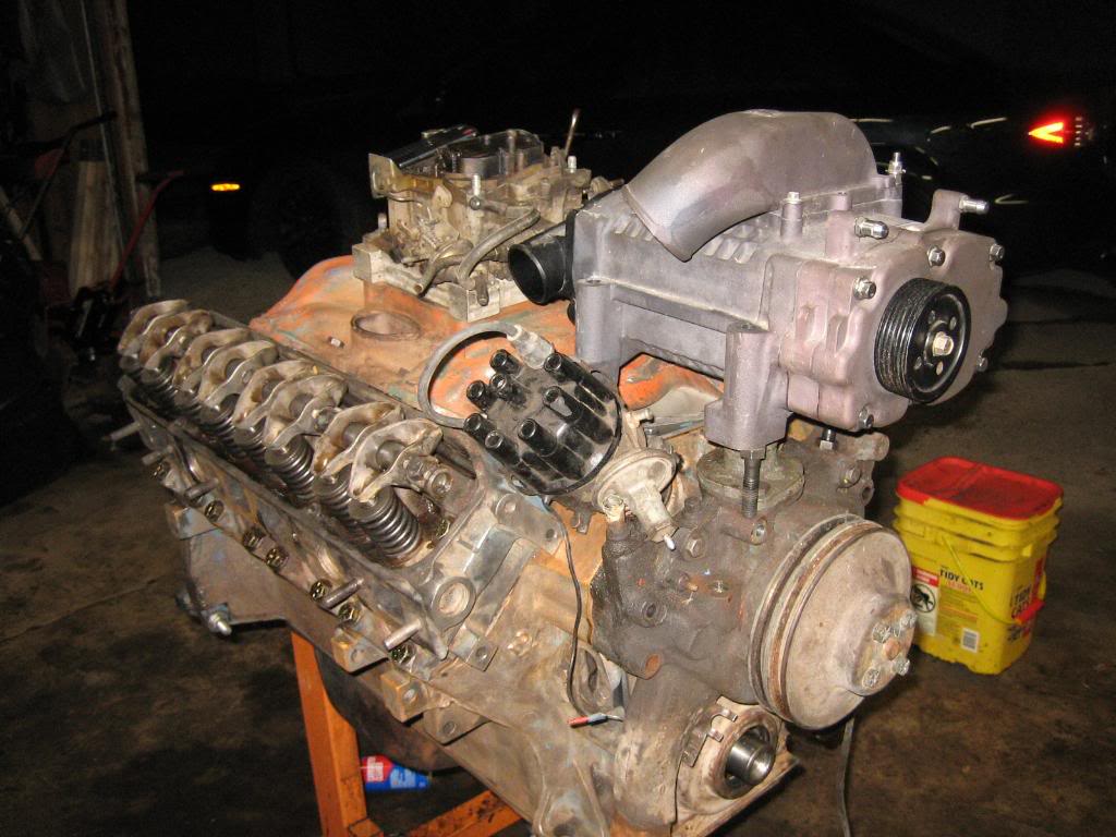
It's been a while since I pulled the Holset and Supercharger out of the closet... so, here they are...
I also sat down and did some math and have some semi-bad news...
P1XV1=P2XV2
So, lets assume that, I want around 6 PSIG, or 20 PSIA of boost from the blower. This is P2. This should make the intake the highest pressure point in the engine, and, make that porting work that I did very, very effective at creating power. Now, let's take the turbos out of the equation to simplify things a bit. So, P1 is the atmospheric pressure, which would be 0 PSIG, or 14PSIA, and V1 is how much volume the blower needs to move, and what we want to figure out...
Now, V2 is the engine displacement, and, the 400 is a 6.55L engine, and I'm going to assume a 6K RPM redline. However, to fill all cylinders at least once, the engine has to make 2 revs, since its a 4 stroke, so in reality, we're only turning 3K... at least how the blower sees it.
Now we have:
P1= 14 PSIA
P2= 20 PSIA
V1= What we want to know
V2= 6.55L per 2 revs, X 3000RPM = 19,650
so, we put this back into the equation, solve for V1, and we get
393,000...
Now, I know the blower moves 1.7L per rev, and I know it has a Max RPM of 14,000.
So, putting that together, for volume I get a max from the blower of only:
23,800 L/Min.
Now, times that by the pressure, and we come up with:
333,200
So, were short, which means the blower is too small for a 6K RPM rev limit. Now, what we can do, is put the max of the blower in, and solve for our engine speed, if we do that, we get:
14X1.7X14,000=20X6.55XS Where S= max RPM of the motor.
Solve for S, and we get:
2563!!!! :shock:
Ah, but, remember, it's 2X, because it's a 4 stroke. Taking that into account, we have about a 5200 RPM redline before the blower begins to loose boost. Now, that doesnt mean we cant spin it to 6K, that just means the blower looses it's ability to compress air past 5200 Crank RPM.
However, one more caveat. We assumed that at 5200 RPM, the blower will be giving it all she's got, so, we are limited to 5200 RPM.
Now, the pulley diameter on the blower is 3". and, we have a drive ratio of:
14000/5000, which is: 2.8:1
2.8:1 is a relatively high belt ratio, but, is still within operational specs for serpetine systems, so, we are good. We are limited to 5K RPM, which, isn't necessarily a bad thing.
This means that I have to find a 6 groove serp pully thats, *gasp* 8.4" in diameter!!! :shock:
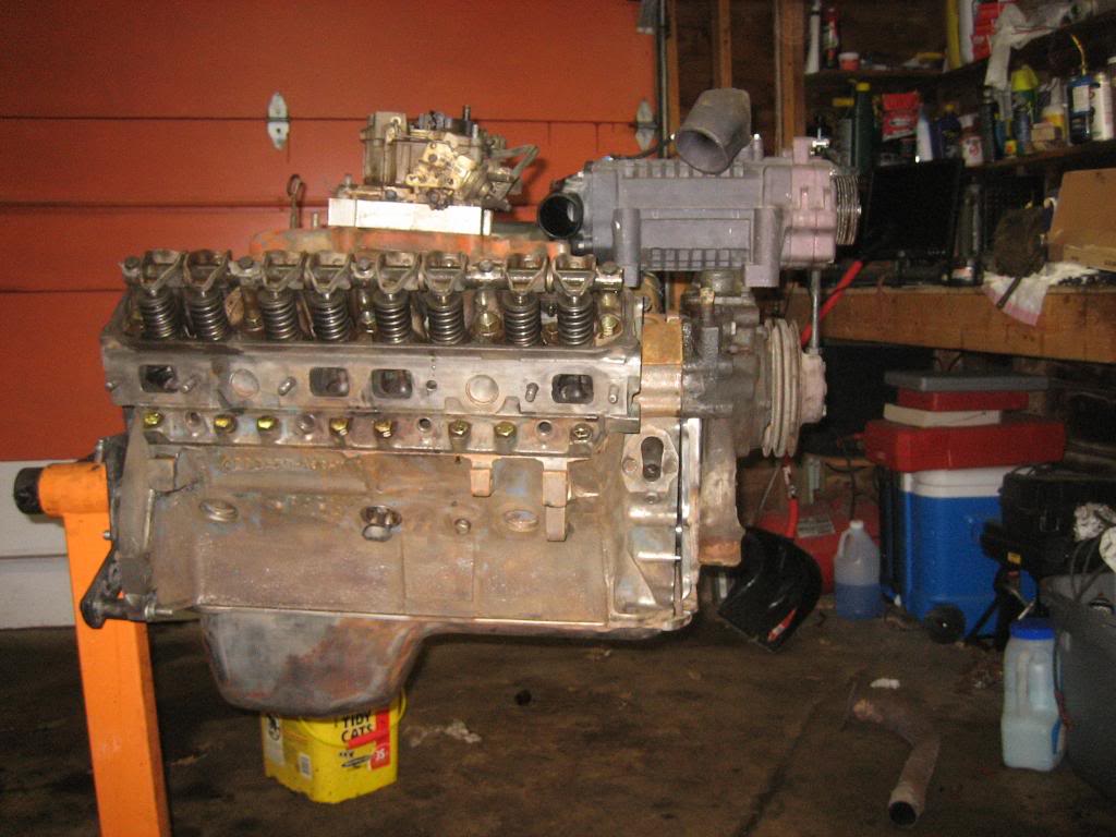
Mocked up in that position, the carb is almost as tall as the blower... should be plenty of hood clearance...
Went ahead and cut the manifold, and mounted it out about 1.5" from teh head, as far out on the factory studs as I could get it... I'll go to the hardware store tomorrow and get some longer bolts so I can mock it up exactly...
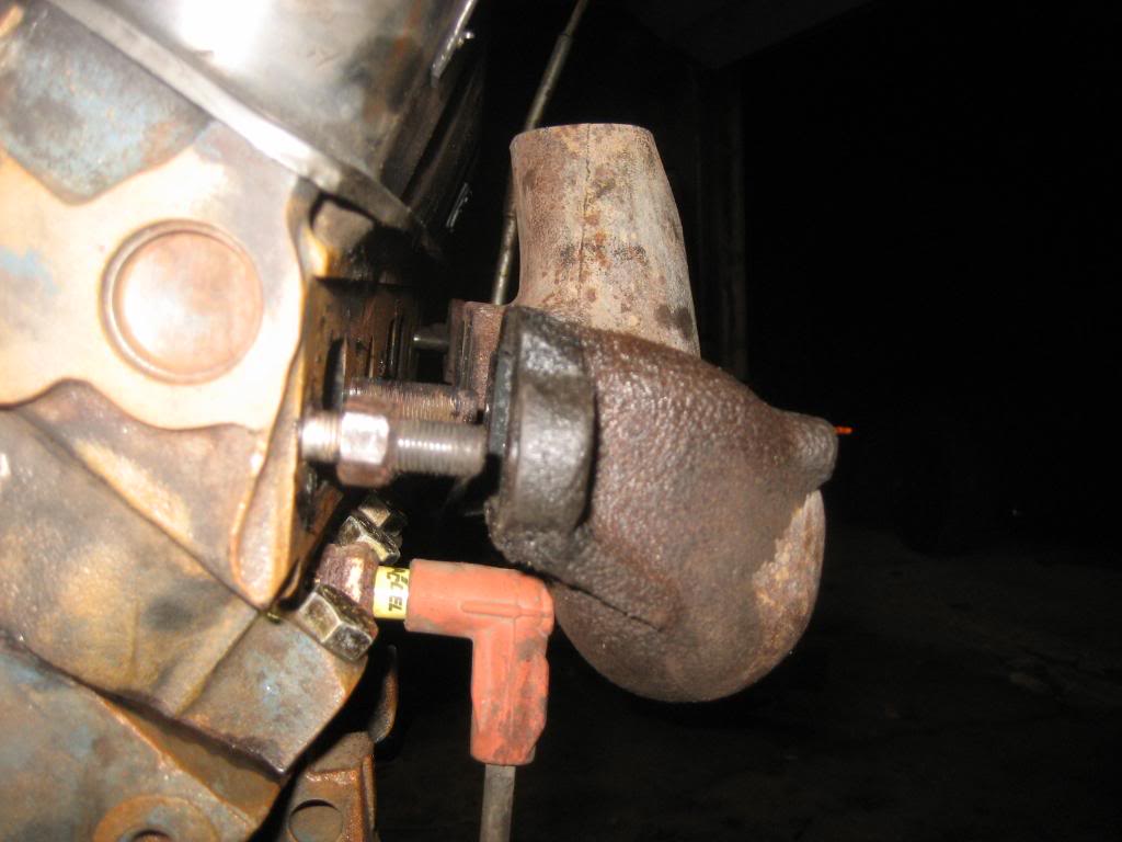
Hmmm, turbo is WAY to high... the flange doesnt fit the manifold very well either...
I'm fully aware that welding Mild cold rolled to cast is very difficult, so, I'll be taking it in and getting a local shop to nickel/Iron braze the 1" thick turbo flange on...
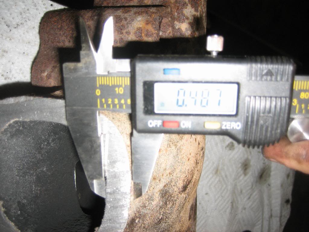
Made a second cut, this time at an angle, and about 1.5" lower...
almost 1/2" of iron to play with... that will hold the heat in well.
Template I made of the turbo flange...

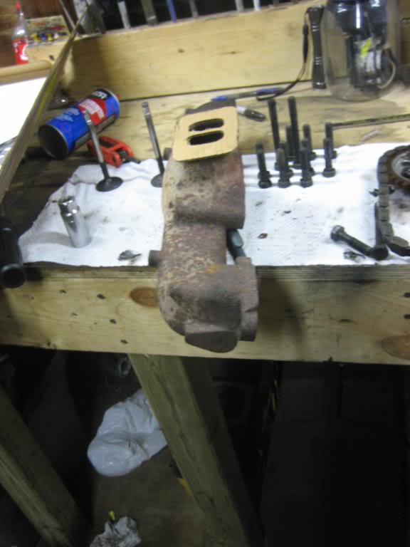
Spark plugs will definitey be needing a heat shield...
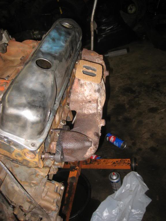
Lets see how they look together...
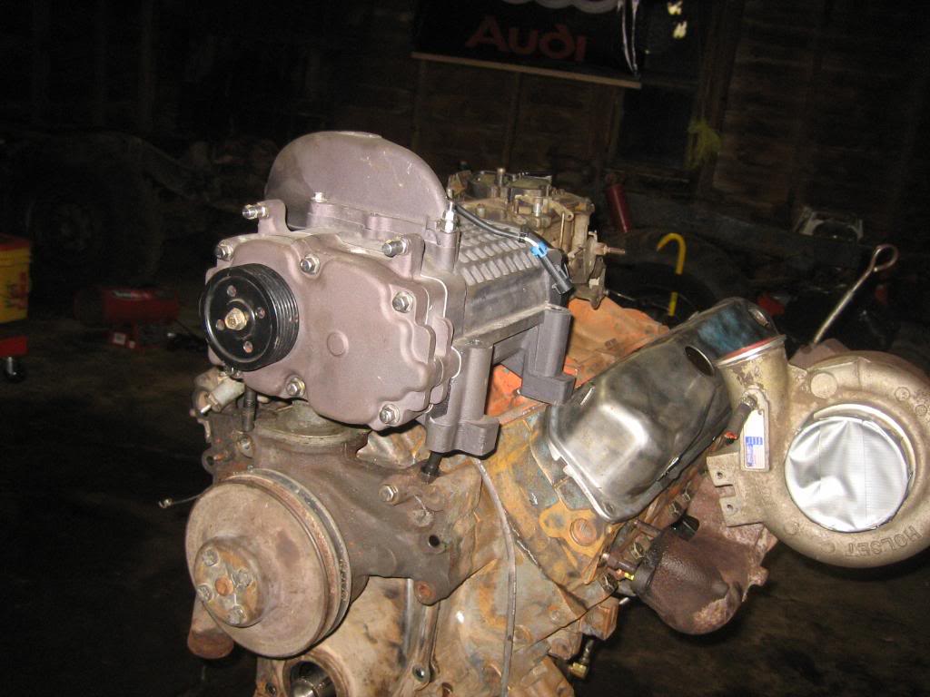
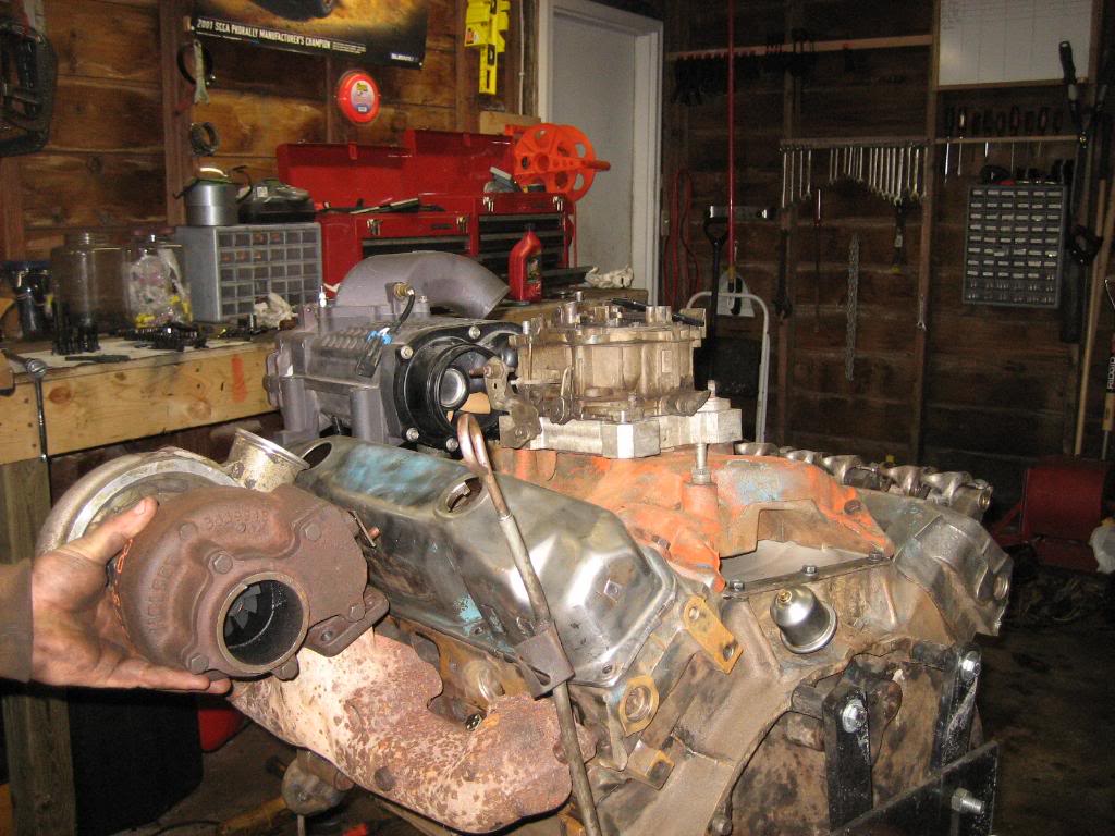
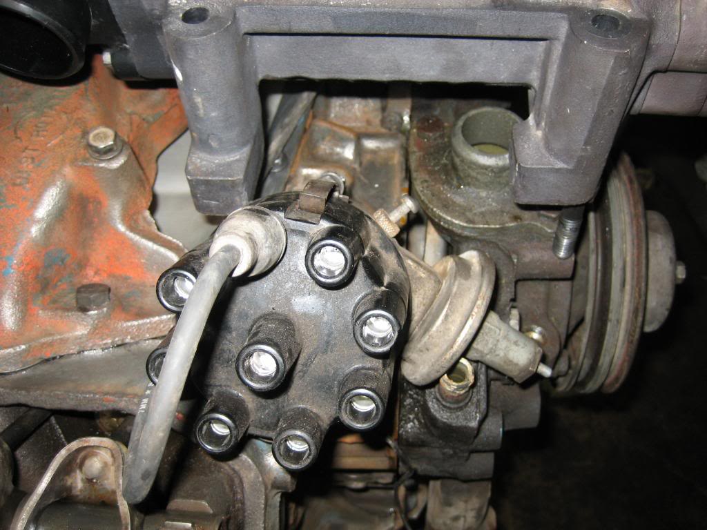
Notice how close I can tuck the turbo outlet for the compressor in to the valve cover... the piping from turbo to supercharger is going to be insanely short.
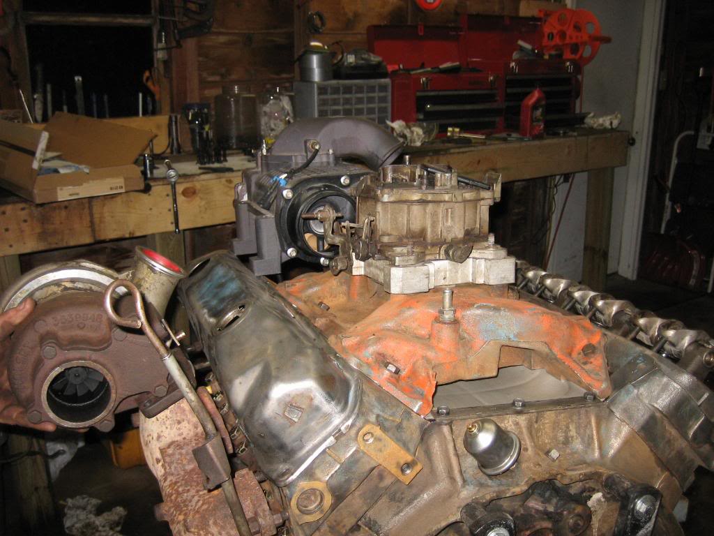
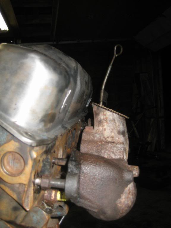
Going to come off both sides and come into the back of the charger. Am going to toss that silly black plastic backing plate and replace it with a steel one with pipes coming in from each side at about 45*. That should just sneak past the carb. In the pic below, I plan on adding a water to air intercooler, where the carb hat will face to the passenger's side head, and the intercooler will be a simple in off the supercharger discharge seen there, make a 90* bend into the core, through the core, then a 90* bend into the carb hat. Again, nice and short plumbing... might not even need to use tubing, might be able to make it all fit with silicone couplers.
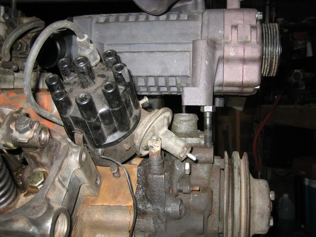
Very, Very tight...

I ended up ordering my Mopar Performance cast valve covers, as well as a nice Comp Cams double roller timing set. I also ordered a fuel pmp block off plate, and the accessory kit for the valve covers.
Anyway, on to the good stuff tonight...
Was looking at the factory manifolds... and something occured to me...
the only issue is that I can't get to the spark plug holes...
However, if I make spacer blocks 2" thick, I can get in to the plugs no problem. The total width of the engine with the spacer blocks, outside of one manifold, to outside of the other will be 30"... same as the frame, and pretty close to what my 360 measured with it's goofy mounts that I made. Near as I can tell, using the stock 1977 cross member will mount it approximately 1-2" lower in the frame, which will be perfect... The plugs will be almost laying on top of the frame.
It's been a while since I pulled the Holset and Supercharger out of the closet... so, here they are...
I also sat down and did some math and have some semi-bad news...
P1XV1=P2XV2
So, lets assume that, I want around 6 PSIG, or 20 PSIA of boost from the blower. This is P2. This should make the intake the highest pressure point in the engine, and, make that porting work that I did very, very effective at creating power. Now, let's take the turbos out of the equation to simplify things a bit. So, P1 is the atmospheric pressure, which would be 0 PSIG, or 14PSIA, and V1 is how much volume the blower needs to move, and what we want to figure out...
Now, V2 is the engine displacement, and, the 400 is a 6.55L engine, and I'm going to assume a 6K RPM redline. However, to fill all cylinders at least once, the engine has to make 2 revs, since its a 4 stroke, so in reality, we're only turning 3K... at least how the blower sees it.
Now we have:
P1= 14 PSIA
P2= 20 PSIA
V1= What we want to know
V2= 6.55L per 2 revs, X 3000RPM = 19,650
so, we put this back into the equation, solve for V1, and we get
393,000...
Now, I know the blower moves 1.7L per rev, and I know it has a Max RPM of 14,000.
So, putting that together, for volume I get a max from the blower of only:
23,800 L/Min.
Now, times that by the pressure, and we come up with:
333,200
So, were short, which means the blower is too small for a 6K RPM rev limit. Now, what we can do, is put the max of the blower in, and solve for our engine speed, if we do that, we get:
14X1.7X14,000=20X6.55XS Where S= max RPM of the motor.
Solve for S, and we get:
2563!!!! :shock:
Ah, but, remember, it's 2X, because it's a 4 stroke. Taking that into account, we have about a 5200 RPM redline before the blower begins to loose boost. Now, that doesnt mean we cant spin it to 6K, that just means the blower looses it's ability to compress air past 5200 Crank RPM.
However, one more caveat. We assumed that at 5200 RPM, the blower will be giving it all she's got, so, we are limited to 5200 RPM.
Now, the pulley diameter on the blower is 3". and, we have a drive ratio of:
14000/5000, which is: 2.8:1
2.8:1 is a relatively high belt ratio, but, is still within operational specs for serpetine systems, so, we are good. We are limited to 5K RPM, which, isn't necessarily a bad thing.
This means that I have to find a 6 groove serp pully thats, *gasp* 8.4" in diameter!!! :shock:
Mocked up in that position, the carb is almost as tall as the blower... should be plenty of hood clearance...
Went ahead and cut the manifold, and mounted it out about 1.5" from teh head, as far out on the factory studs as I could get it... I'll go to the hardware store tomorrow and get some longer bolts so I can mock it up exactly...
Hmmm, turbo is WAY to high... the flange doesnt fit the manifold very well either...
I'm fully aware that welding Mild cold rolled to cast is very difficult, so, I'll be taking it in and getting a local shop to nickel/Iron braze the 1" thick turbo flange on...
Made a second cut, this time at an angle, and about 1.5" lower...
almost 1/2" of iron to play with... that will hold the heat in well.
Template I made of the turbo flange...
Spark plugs will definitey be needing a heat shield...
Lets see how they look together...
Notice how close I can tuck the turbo outlet for the compressor in to the valve cover... the piping from turbo to supercharger is going to be insanely short.
Going to come off both sides and come into the back of the charger. Am going to toss that silly black plastic backing plate and replace it with a steel one with pipes coming in from each side at about 45*. That should just sneak past the carb. In the pic below, I plan on adding a water to air intercooler, where the carb hat will face to the passenger's side head, and the intercooler will be a simple in off the supercharger discharge seen there, make a 90* bend into the core, through the core, then a 90* bend into the carb hat. Again, nice and short plumbing... might not even need to use tubing, might be able to make it all fit with silicone couplers.
Very, Very tight...
Thread Starter
1.0 BAR
Joined: Feb 2003
Posts: 461
From: Wisconsin
Sent out two autocad files to a local machine shop for a quote on the flanges and manifold spacers. Flanges are 1" thick, and the spacers will be 2" thick. Reason for the thikc turbo flanges is to help minimize the heat concentration at the weld between teh cast and the steel. I could make them myself, but, I really would rather just pay to have it done, as cutting through 2" of steel doesn't exactly sound fun...
Thread Starter
1.0 BAR
Joined: Feb 2003
Posts: 461
From: Wisconsin
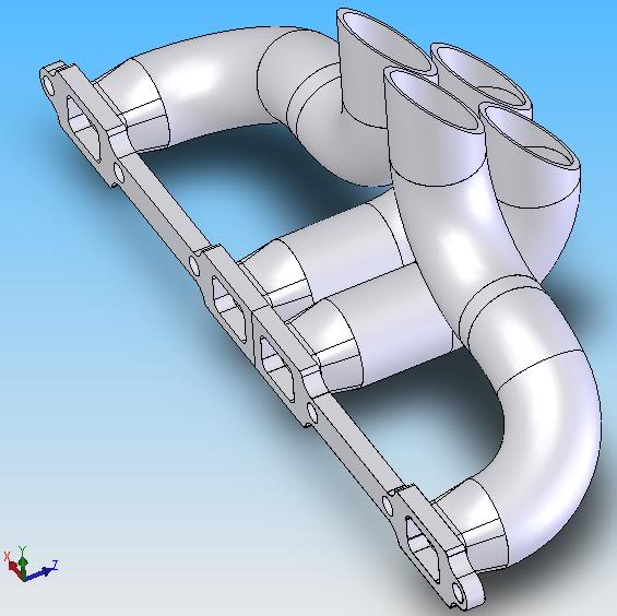
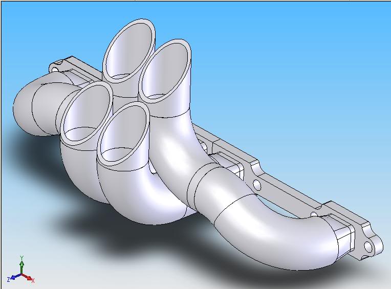
Going to build my own headers now... Crazy assed machine shop wants 1K bucks to cut spacers!! I'm working on the 3D solidworks header model now...
Well, after more thinking, I've decided to scrap the blower... Well, not literally, just, on the Power Wagon. Reason being is, is that I would have to cook up a drive system for it, as the 400 is not serpentine belt, which is not going to be easy or cheap, and, that blower is used, very hard to find, and expensive (A new one from Mercury is 4K bucks!!!!). I would hate to put a ton of $$ into getting it on there, only to find I have a problem with it the first time it runs. So, I'll hang onto it for the mean time... Might use it on a future project where geting it on there is less labor intensive. Besides, the twin turbos will make more than enough power for what I plan on doing.
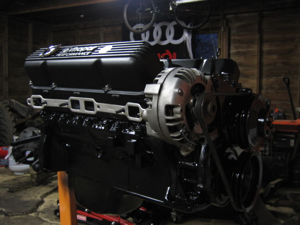
Got more work done...
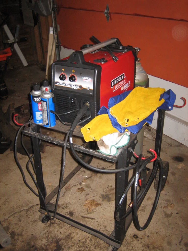
My new toy...
Comp Cams timing set. Very nice peice for the $50
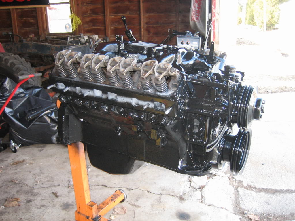
Finally, paint!
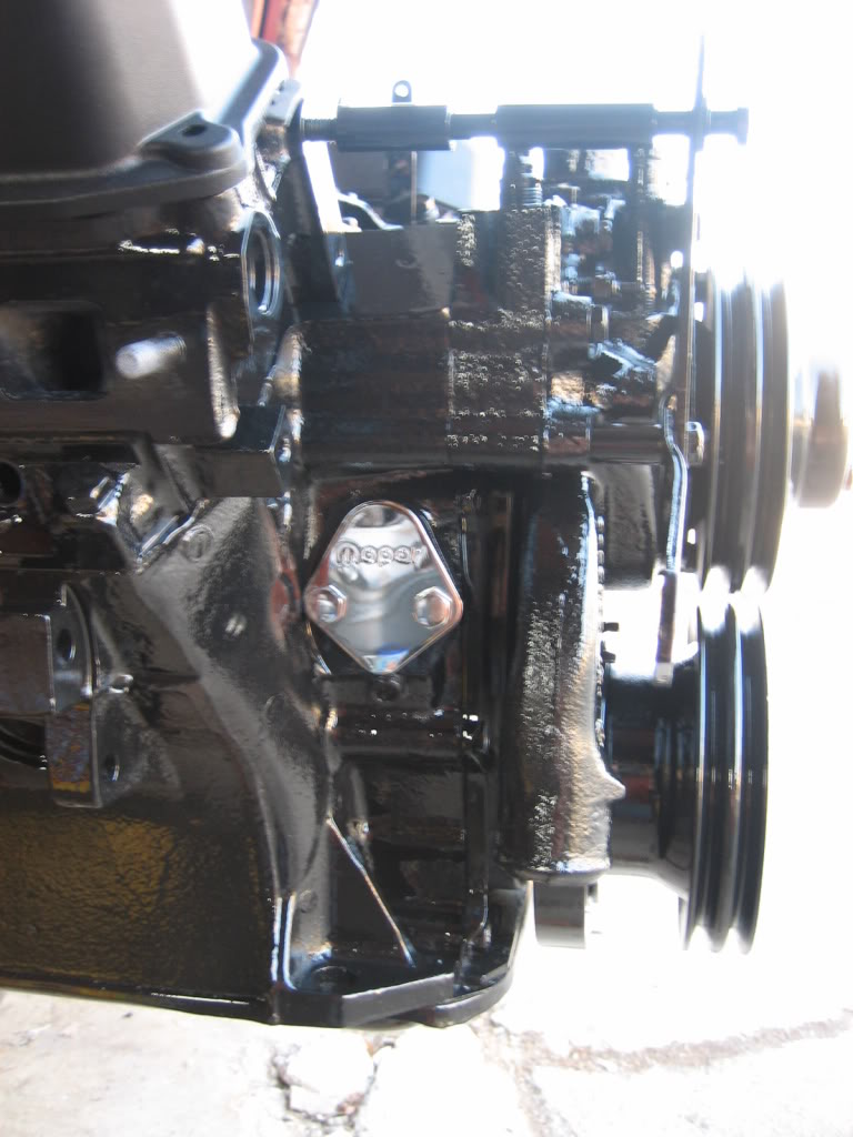
Mopar Performance fuel pump block off plate. Wont be needing the mechanical one... it doesnt move enough fuel for my goals... :shock:
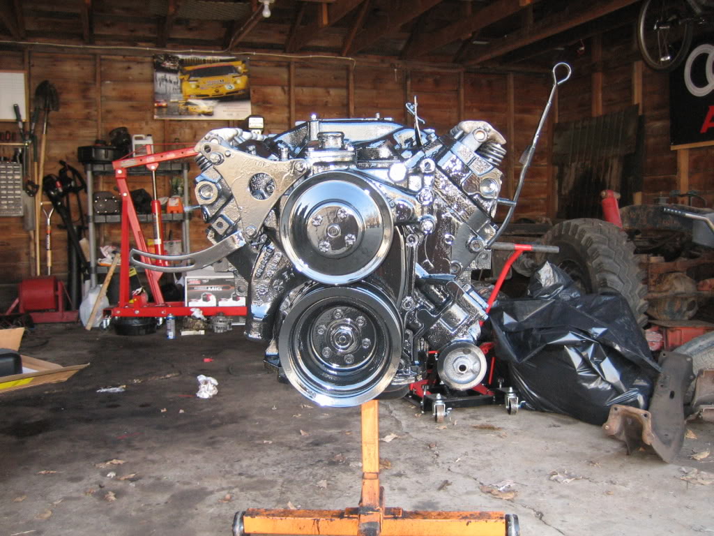
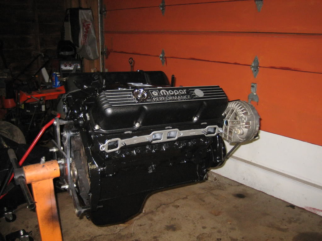
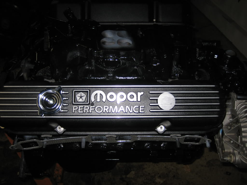
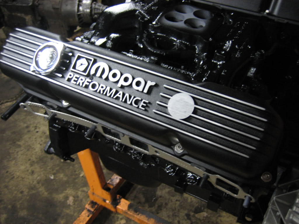
The new covers:
Stainless, allen head bolts and washers:
Alternator cleaned up well... lets just hope it still works after its soapy water bath... lol
Well, after more thinking, I've decided to scrap the blower... Well, not literally, just, on the Power Wagon. Reason being is, is that I would have to cook up a drive system for it, as the 400 is not serpentine belt, which is not going to be easy or cheap, and, that blower is used, very hard to find, and expensive (A new one from Mercury is 4K bucks!!!!). I would hate to put a ton of $$ into getting it on there, only to find I have a problem with it the first time it runs. So, I'll hang onto it for the mean time... Might use it on a future project where geting it on there is less labor intensive. Besides, the twin turbos will make more than enough power for what I plan on doing.
Got more work done...
My new toy...
Comp Cams timing set. Very nice peice for the $50
Finally, paint!
Mopar Performance fuel pump block off plate. Wont be needing the mechanical one... it doesnt move enough fuel for my goals... :shock:
The new covers:
Stainless, allen head bolts and washers:
Alternator cleaned up well... lets just hope it still works after its soapy water bath... lol
Thread Starter
1.0 BAR
Joined: Feb 2003
Posts: 461
From: Wisconsin
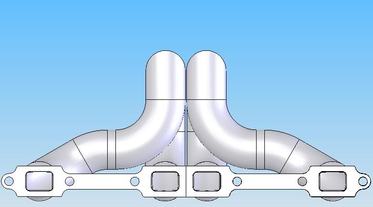
Finished the 3D model of the header... not exactly what I plan to do, but close. Mainly, I plan on merging the 4 tubes into one where they form the collector, but, I didn't want to spend the time trying to draw it...

Thread Starter
1.0 BAR
Joined: Feb 2003
Posts: 461
From: Wisconsin
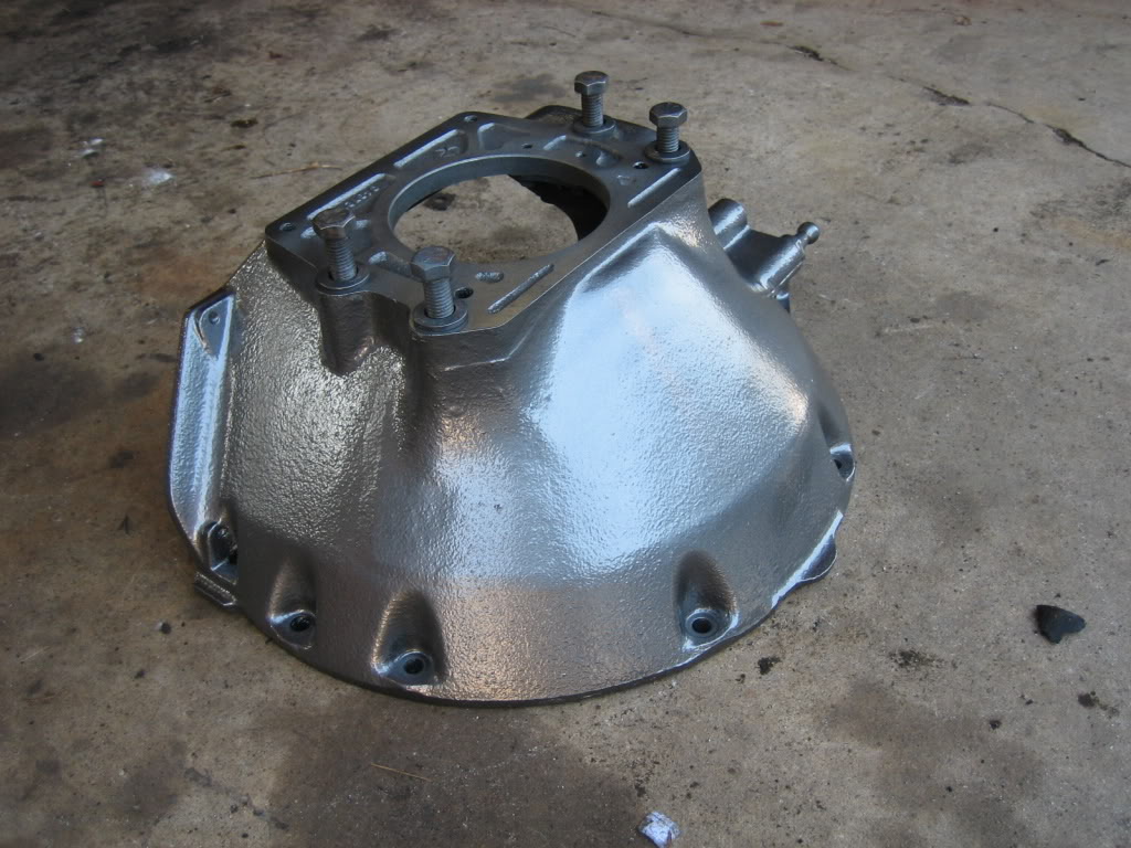
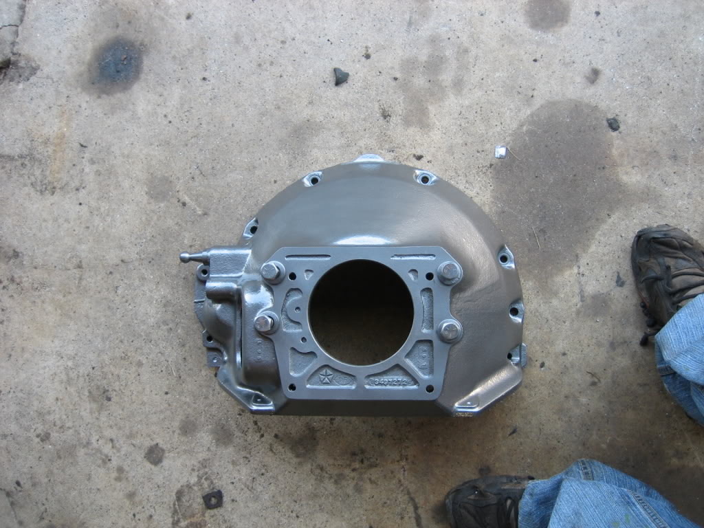
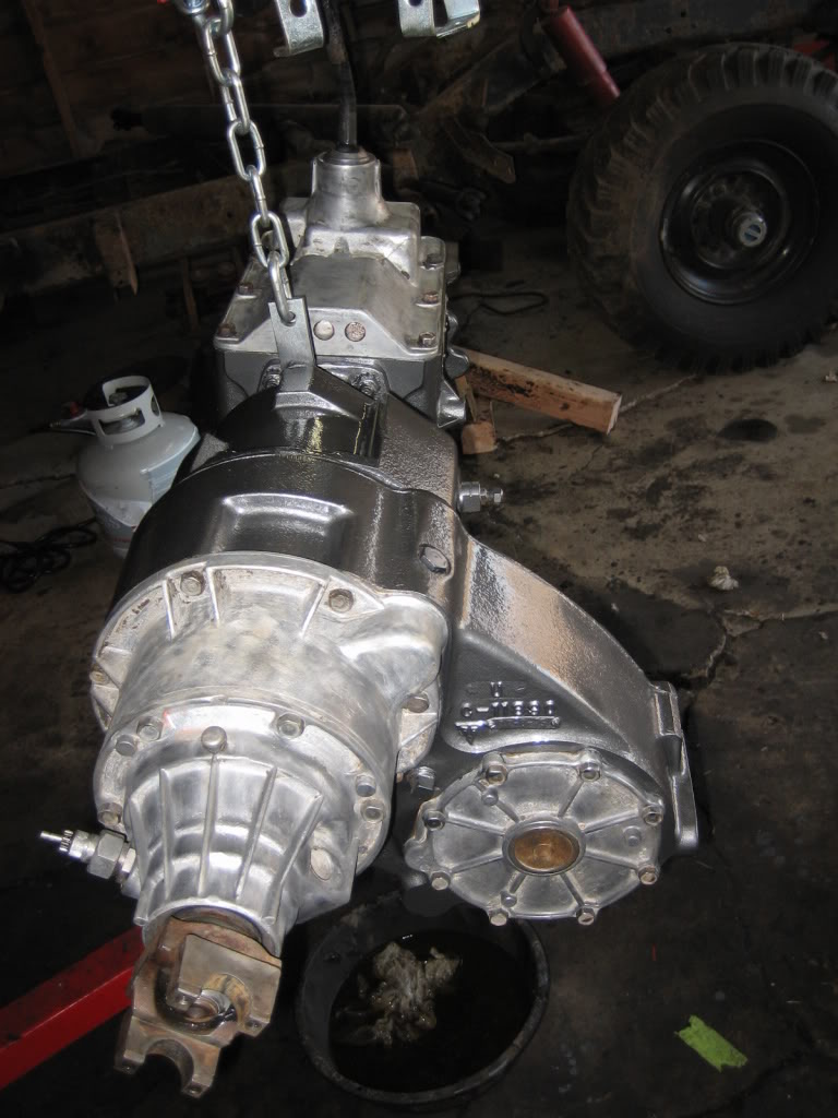
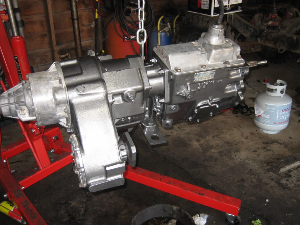
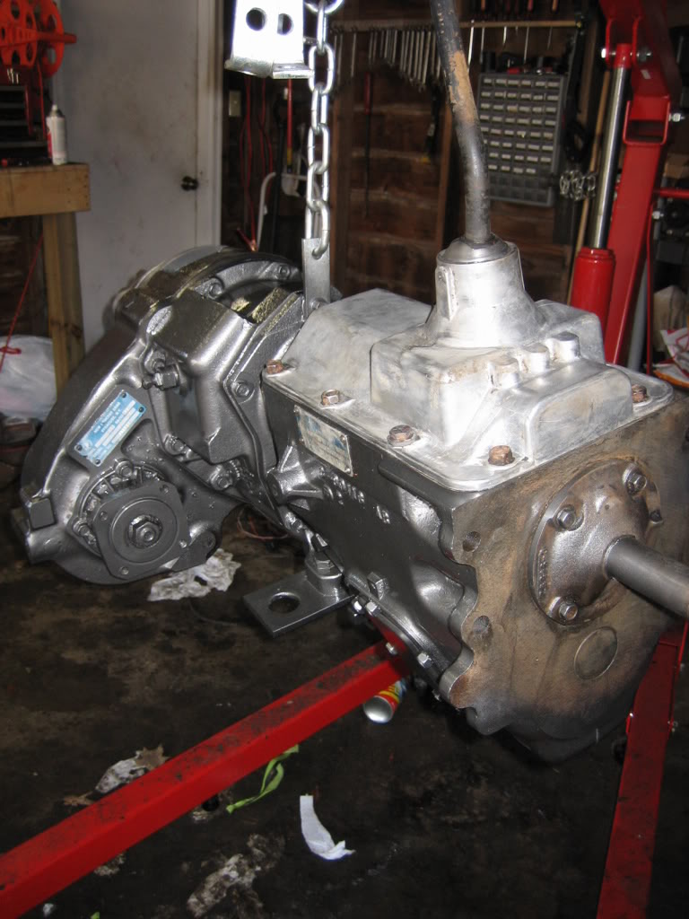
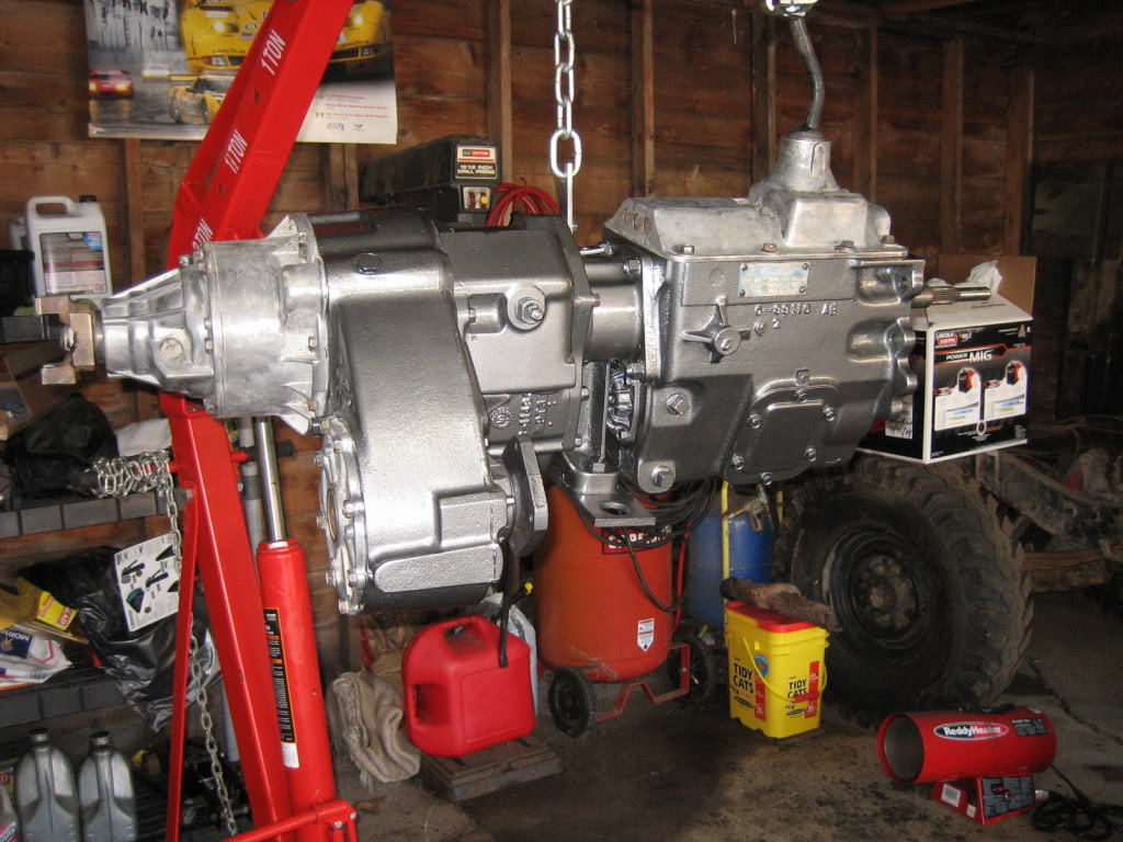
Finally got the transmission and T case cleaned and painted. Need a new rear seal for the transfer case output, the one in there is toast. On a side note, this is the color I have in mind for the body... Dark, graphite grey metalic with black fenders. I'm going to go a bit darker then this is...

Thread Starter
1.0 BAR
Joined: Feb 2003
Posts: 461
From: Wisconsin
haven't had time to work on the truck, let alone an update until tonight. Work has me pretty busy... seems the demands keep piling up, but the pay ain't budging. I'm happy to have a job though.
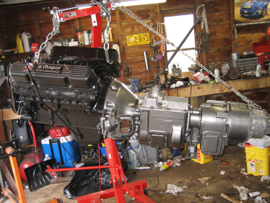
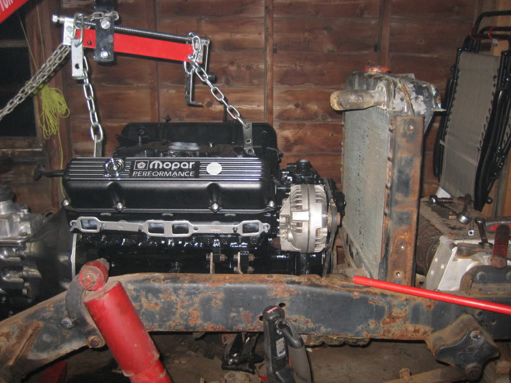
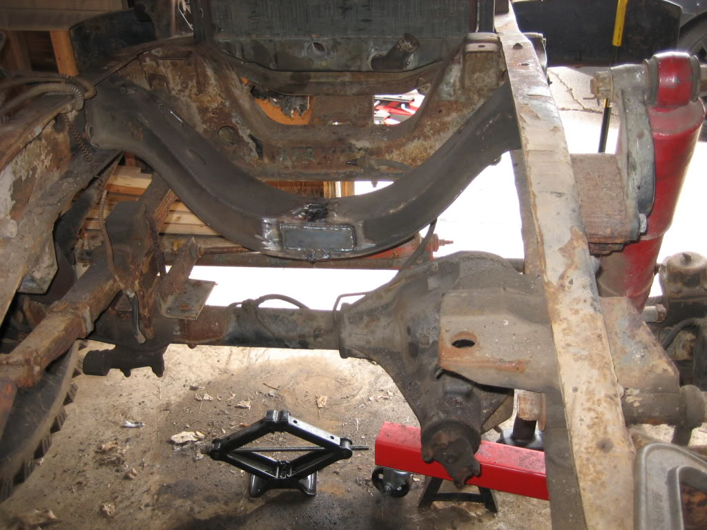
The engine is officially resting in the frame tonight! I havent gotten my clutch yet, or run the turbo oil lines, so it will have to come back out, but, I am in the process of getting the mounts and such all set up so that I can begin disassembling the frame and cleaning and painting it.
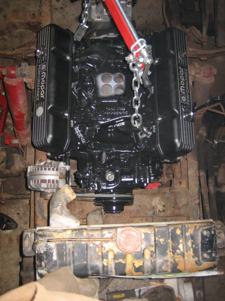
drivetrain back together... I know, my garage is a mess...
getting it in the rough position:
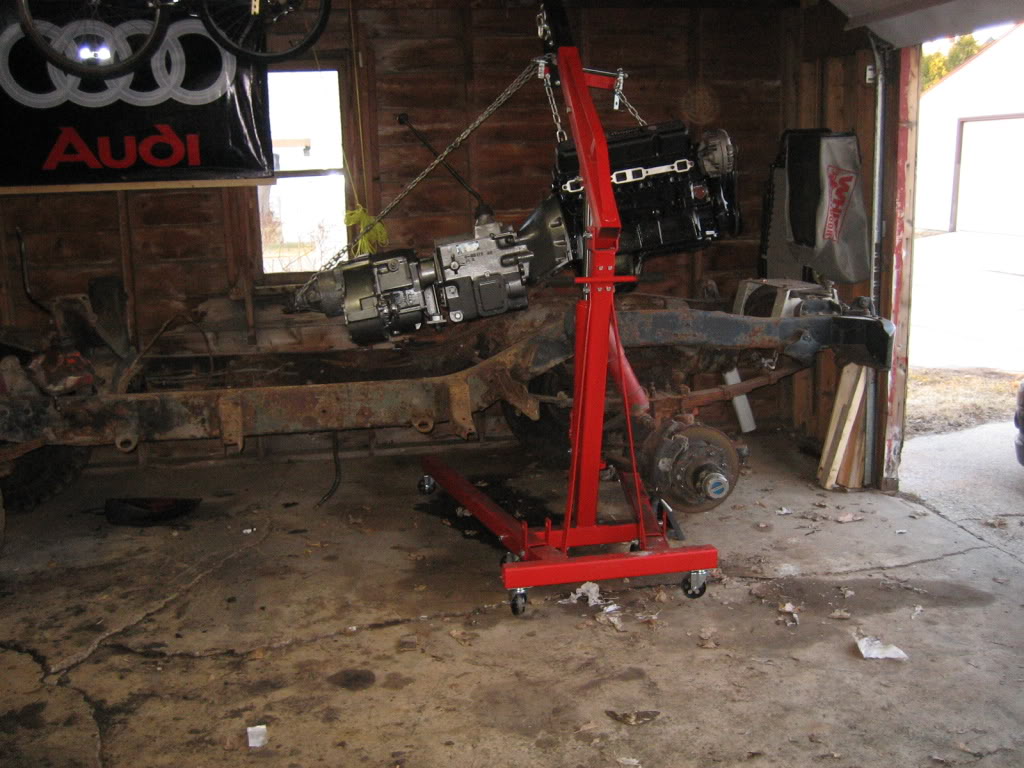
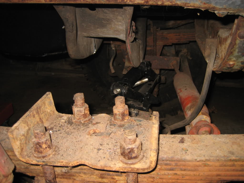
the 1977 engine mount fits like a glove... I had to cut it in 1/2 to get it in the frame.
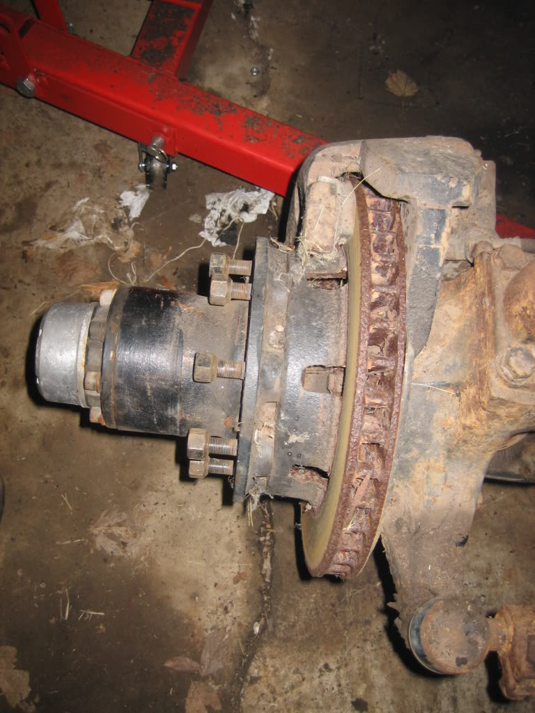
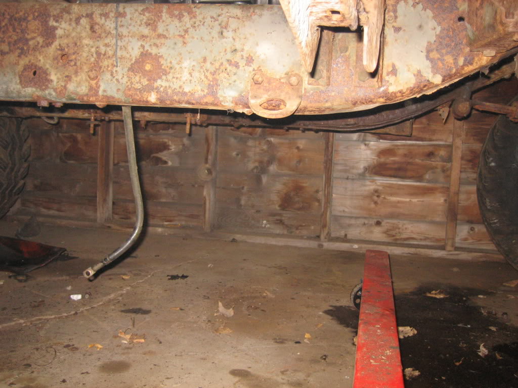
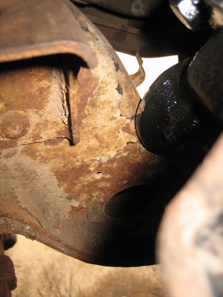
Brakes will definitely need some attentiion...
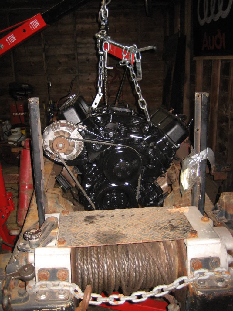
Initial position... Looks OK... measurements say very close to the same position as the 360, but, I think I can do better...
here is the biggest issue...
chains are slack!
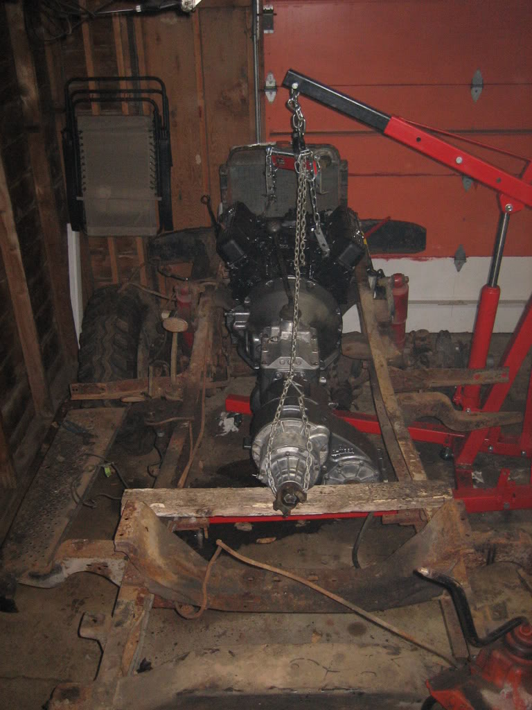
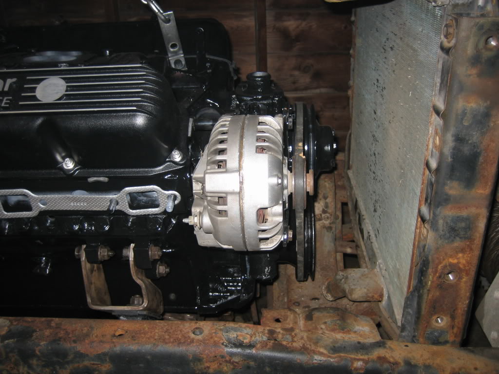
notice how far back I had to move the mount to prevent the radiator from hitting the pulley...
everything will be at frame level, or above...
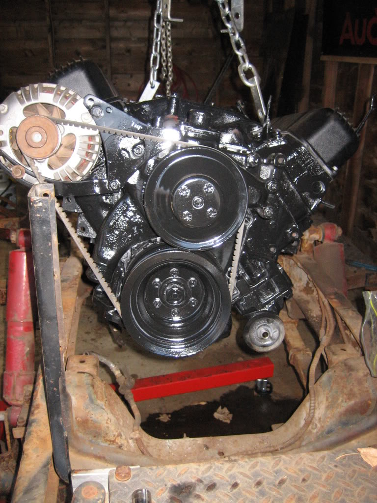
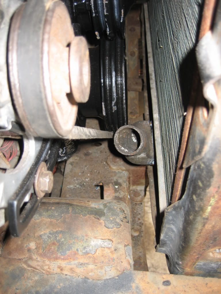
WAAAY too much space between the radiator and pulleys. I leave it like that it will hit the firewall...
Soooo, I lopped the bottom spout off...
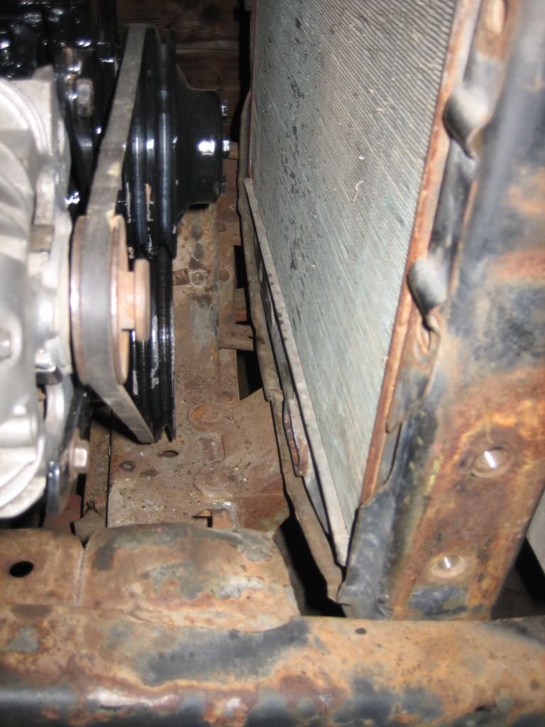
and cut a few inches out of it. Notice now, that the end of the spout is in line with the water pump pulley. I can move the engine forward at least 2" now... giving me the firewall clearance I need.

The engine is officially resting in the frame tonight! I havent gotten my clutch yet, or run the turbo oil lines, so it will have to come back out, but, I am in the process of getting the mounts and such all set up so that I can begin disassembling the frame and cleaning and painting it.
drivetrain back together... I know, my garage is a mess...
getting it in the rough position:
the 1977 engine mount fits like a glove... I had to cut it in 1/2 to get it in the frame.
Brakes will definitely need some attentiion...
Initial position... Looks OK... measurements say very close to the same position as the 360, but, I think I can do better...
here is the biggest issue...
chains are slack!
notice how far back I had to move the mount to prevent the radiator from hitting the pulley...
everything will be at frame level, or above...
WAAAY too much space between the radiator and pulleys. I leave it like that it will hit the firewall...
Soooo, I lopped the bottom spout off...
and cut a few inches out of it. Notice now, that the end of the spout is in line with the water pump pulley. I can move the engine forward at least 2" now... giving me the firewall clearance I need.
Thread Starter
1.0 BAR
Joined: Feb 2003
Posts: 461
From: Wisconsin
more work done this morning. Things are looking relatively good... A few small issues, but no biggies, and I've gotten lucky with a few things as well:
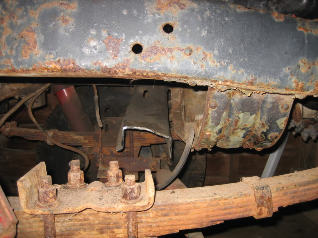
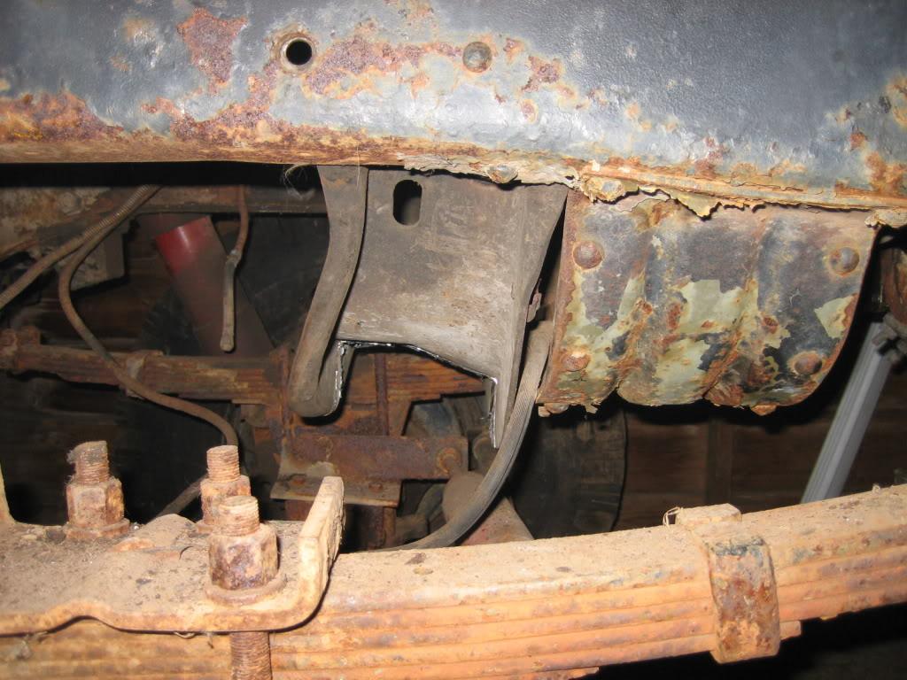
Got the engine mount all welded up. Fish plated it on both sides where I cut it to give it some more strength, as well as welding it on both sides... I dont think its goin anywhere!
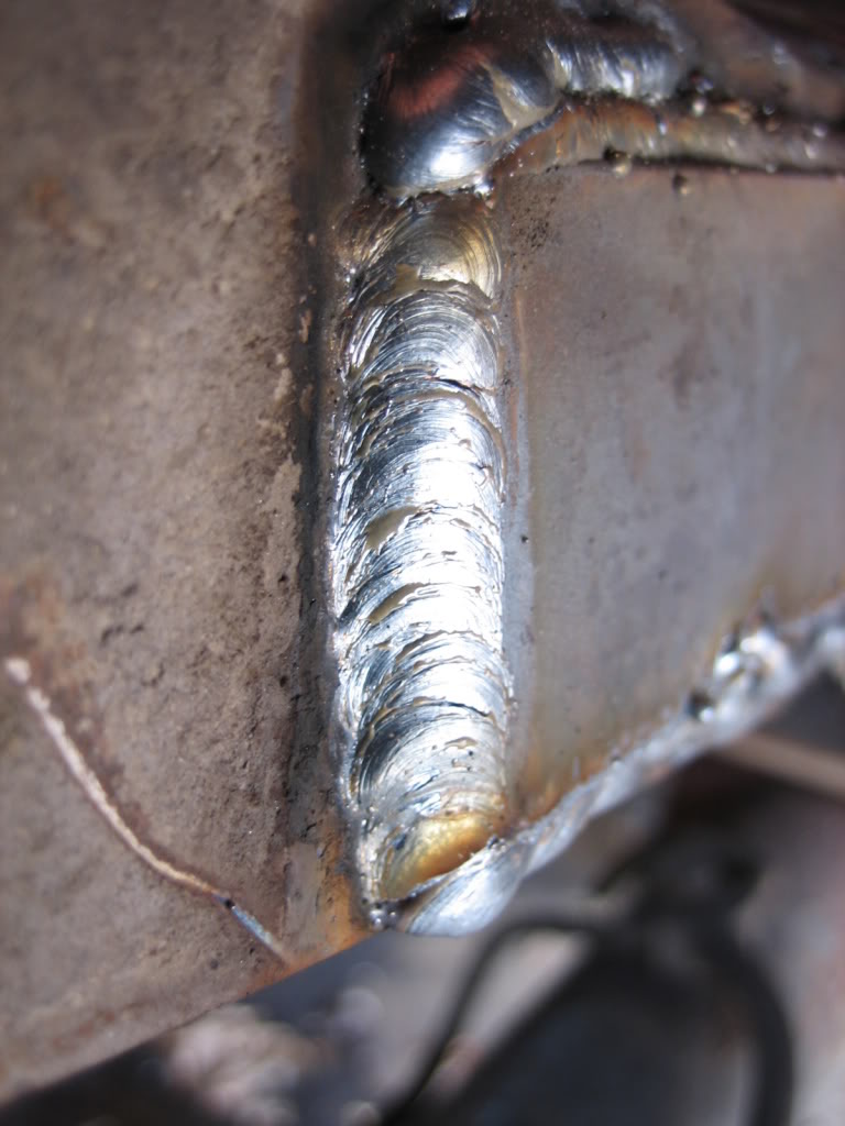
Line across the top is not the joint, its where the weld didnt grind down completely flat... I fixed it since this pic:
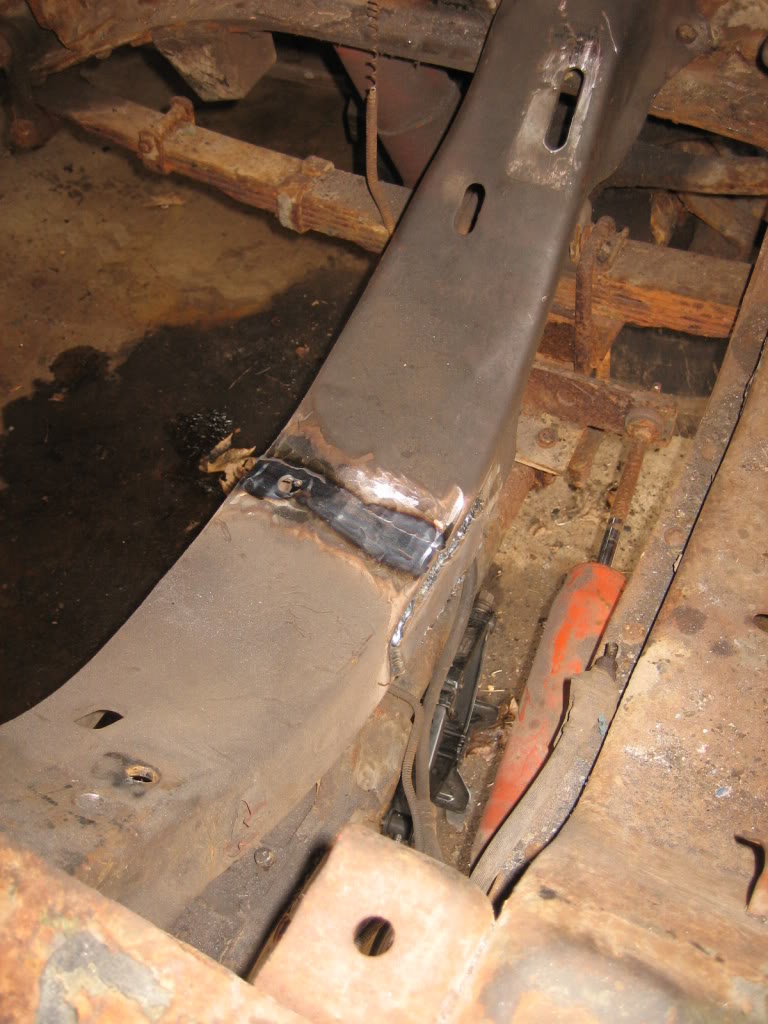
Not bad for a 110V machine on 1/4" steel:
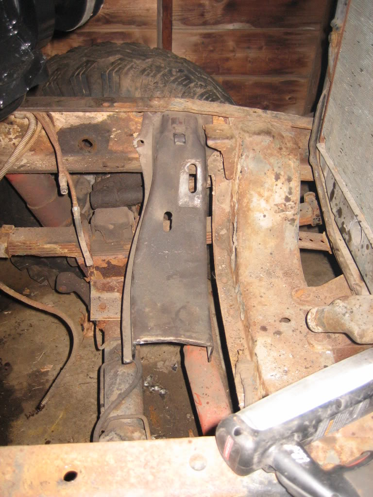
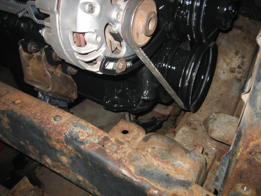
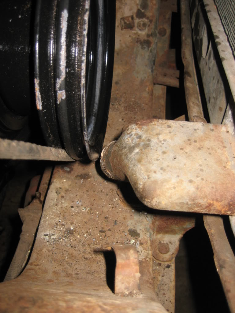
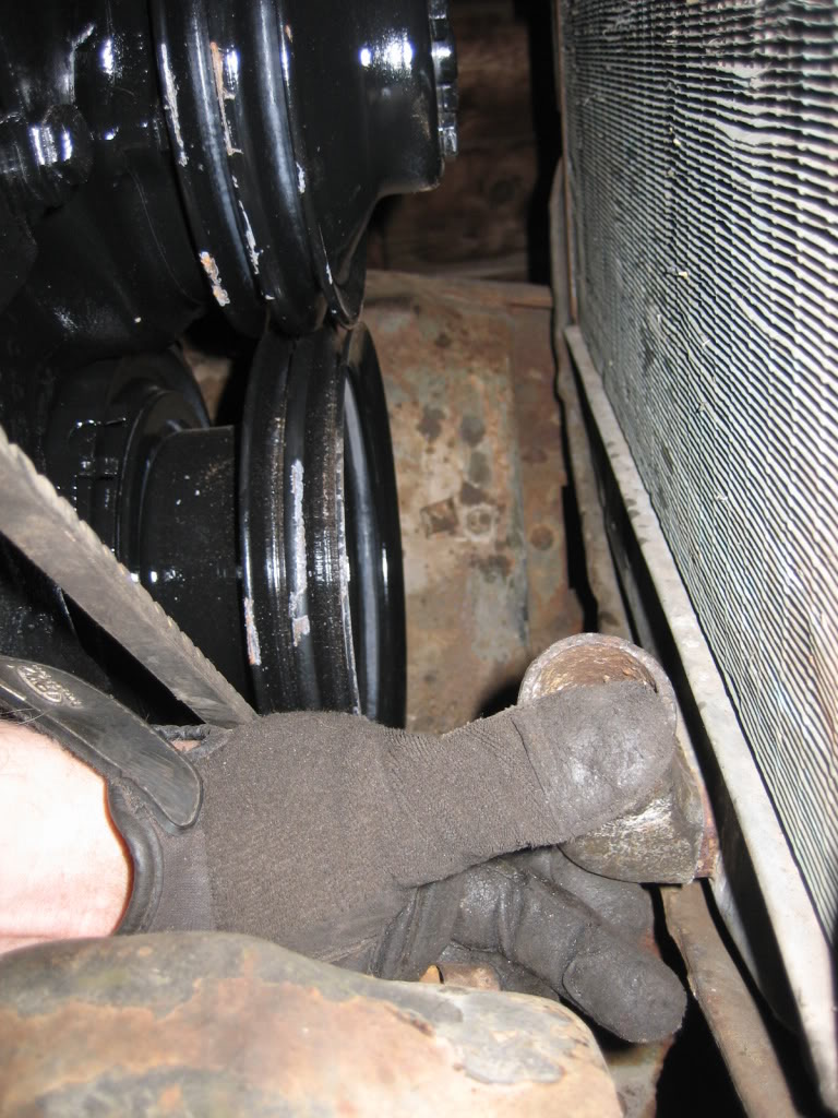
My current issue:
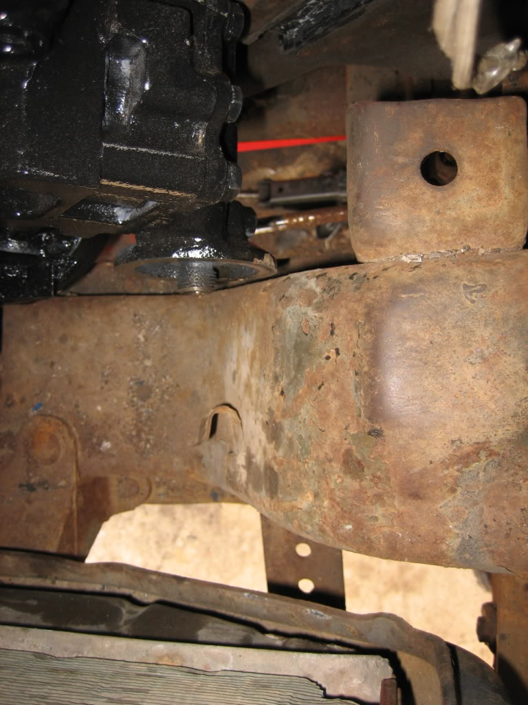
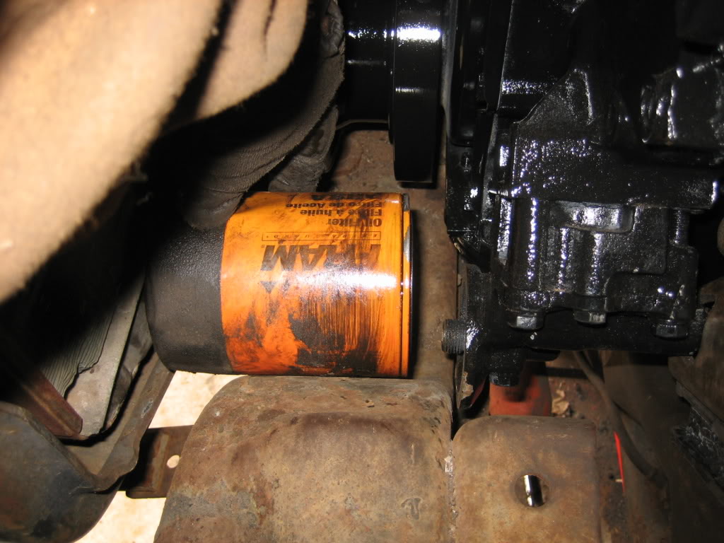
My plan is to get some steel tube about 1" bigger in diameter then the filter, cut a slot in the cross member the size I need for the fiter to clear, and then weld in a section of the tube to fill in the hole, so the cross-member will be "scalloped" where the filter goes, giving me the clearance to put the filter on and take it off from the crossmember.
Got the fit with the radiator a littler better....

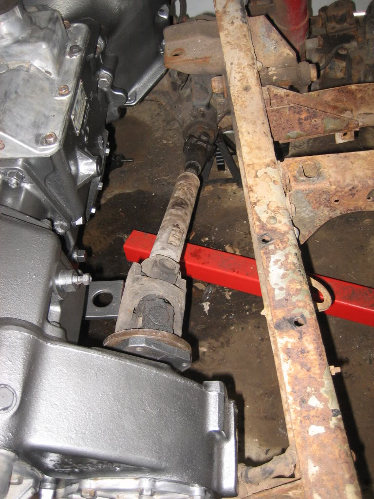
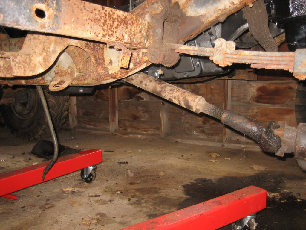
Some VERY good news... the stock 77 front prop shaft will bolt right in!!
Got the engine mount all welded up. Fish plated it on both sides where I cut it to give it some more strength, as well as welding it on both sides... I dont think its goin anywhere!
Line across the top is not the joint, its where the weld didnt grind down completely flat... I fixed it since this pic:
Not bad for a 110V machine on 1/4" steel:
My current issue:
My plan is to get some steel tube about 1" bigger in diameter then the filter, cut a slot in the cross member the size I need for the fiter to clear, and then weld in a section of the tube to fill in the hole, so the cross-member will be "scalloped" where the filter goes, giving me the clearance to put the filter on and take it off from the crossmember.
Got the fit with the radiator a littler better....
Some VERY good news... the stock 77 front prop shaft will bolt right in!!


