Power Wagon Rebuild (Update: 11/5/08)

 11-22-2009, 08:58 PM
#162
1.0 BAR
Thread Starter

Join Date: Feb 2003
Location: Wisconsin
Posts: 461
Some more work done.
I rebuilt the steering box. was in desperate need of it. I also tapped the box for the power assist cylinder lines.
Also:
Redesigned my intake manifold, after reading this:
Turbo Intake Plenum - HybridZ
I plan on adding the fins through the slot, as he did, but, modeling them would have been a beast. I still haven't figured out how he did it, exactly!
I also have a trick up my sleeve on how I'm going to make them... you'll see further down.
One last addition is this, as well:
Laminova Production AB
They are VERY unique in how they function. A typical intercooler core relies on turbulent flow to get the most heat transfer, whereas with all the fins, a Laminova core is much, much more efficient due to the laminar flow of the air over the fins. I havent nailed down completely yet how I'm going to make them fit, but I've got a few ideas. Anyway, here are some pictures:
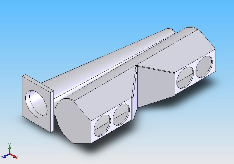
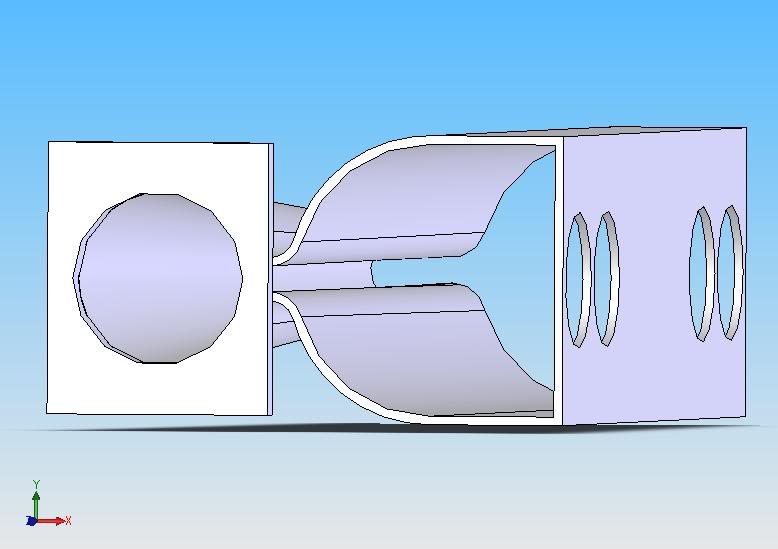
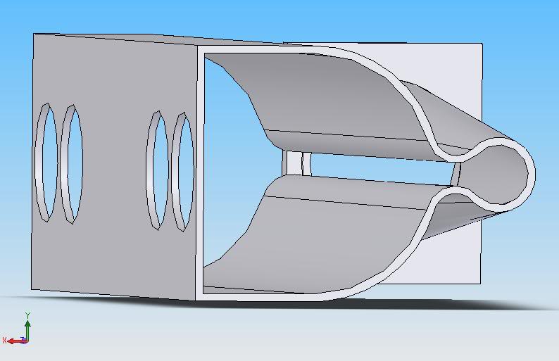
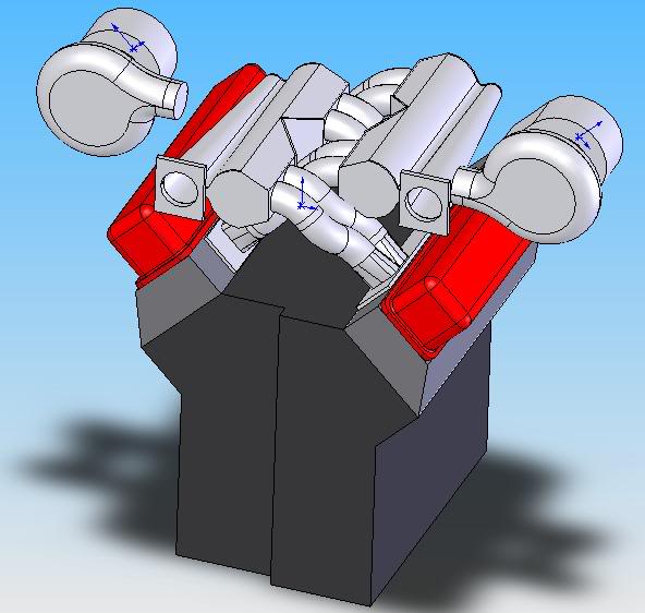
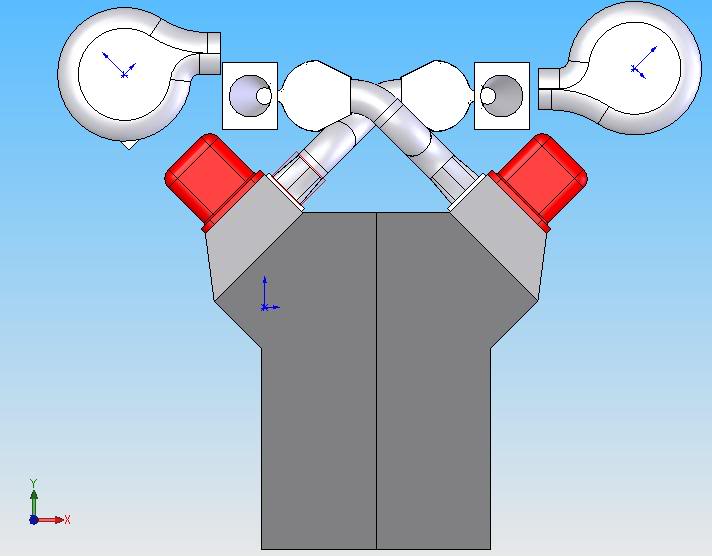
As you all can tell from the model, that is one hellaciously complicated hunk of modern art/intake plenum. As such, I know anything I try to weld up will look terrible
so.....
I'm going to cast them.
First step is to make a positive mold. After a bit of debating, I decided to do a wood mold, as I have a decent array of wood tools (another one of my hobbies) and A wood mold is infinately reusable, so long as I am gentle with it. This way, if I dont get the gating or risers right, I simple cast another plaster mold around my wooden model and keep pouring till I get it right.
So, I started out by ripping a 2X4 dow to 14" long chunks squared off at 1.5"X2.75".
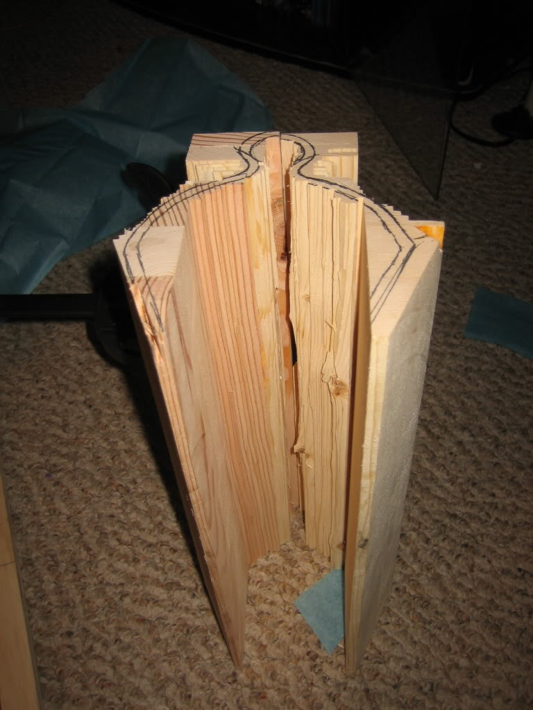
I glued 6 of these together, then another 6 to form two 14"X6"X2.75" blocks. The seam in between them is not glued, and that is intentional, you'll see why in a bit.
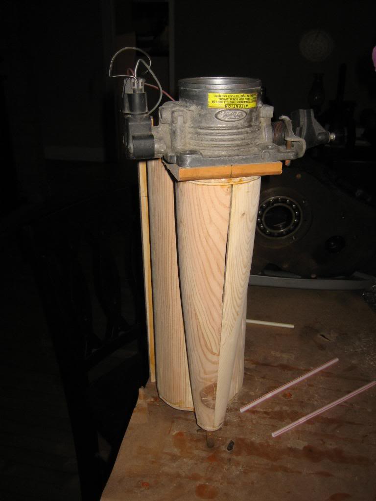
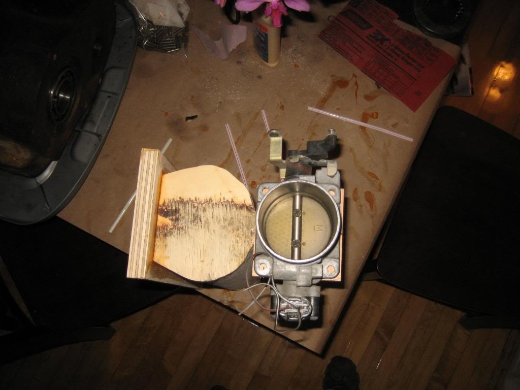
I then traced the respective patterns on each end using dimensions from teh computer model. Unfortunately, I dont have a printer, otehrwise I would have just printed each end view, cut it out, and glued it on. For Throttle Bodies, I'm going to use a pair of ford 65mm Mustang 4.6L bodies I got at my local you pull it yard for $10 each. 65mm is 2.55 inches, perforct for the 2.5: discharge out of the Holset turbos.
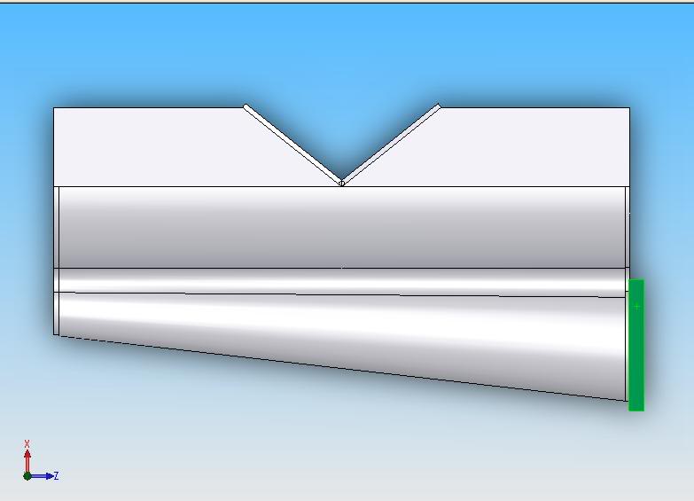
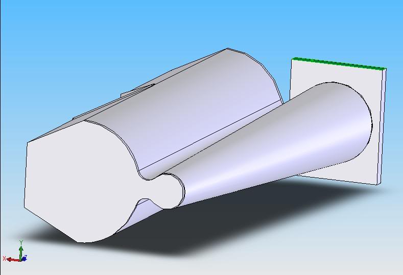
TB end:
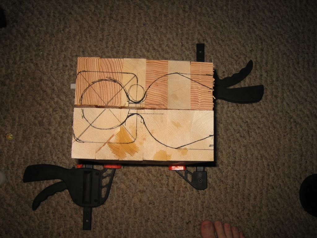
Opposite end:
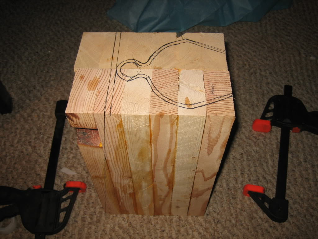
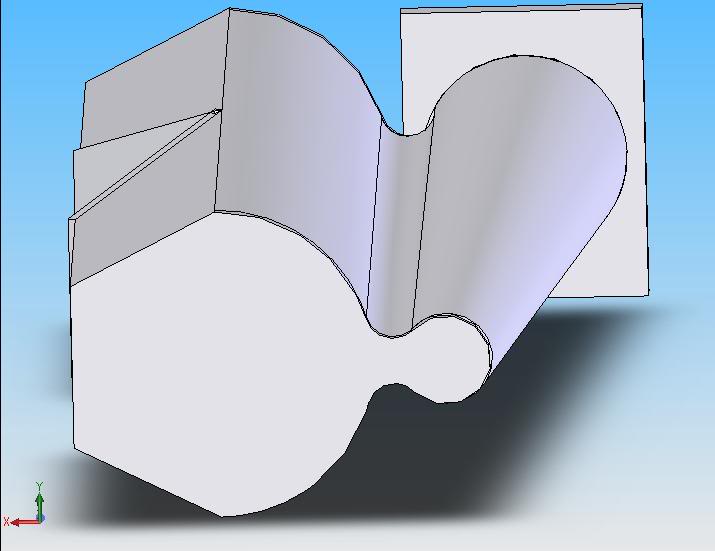
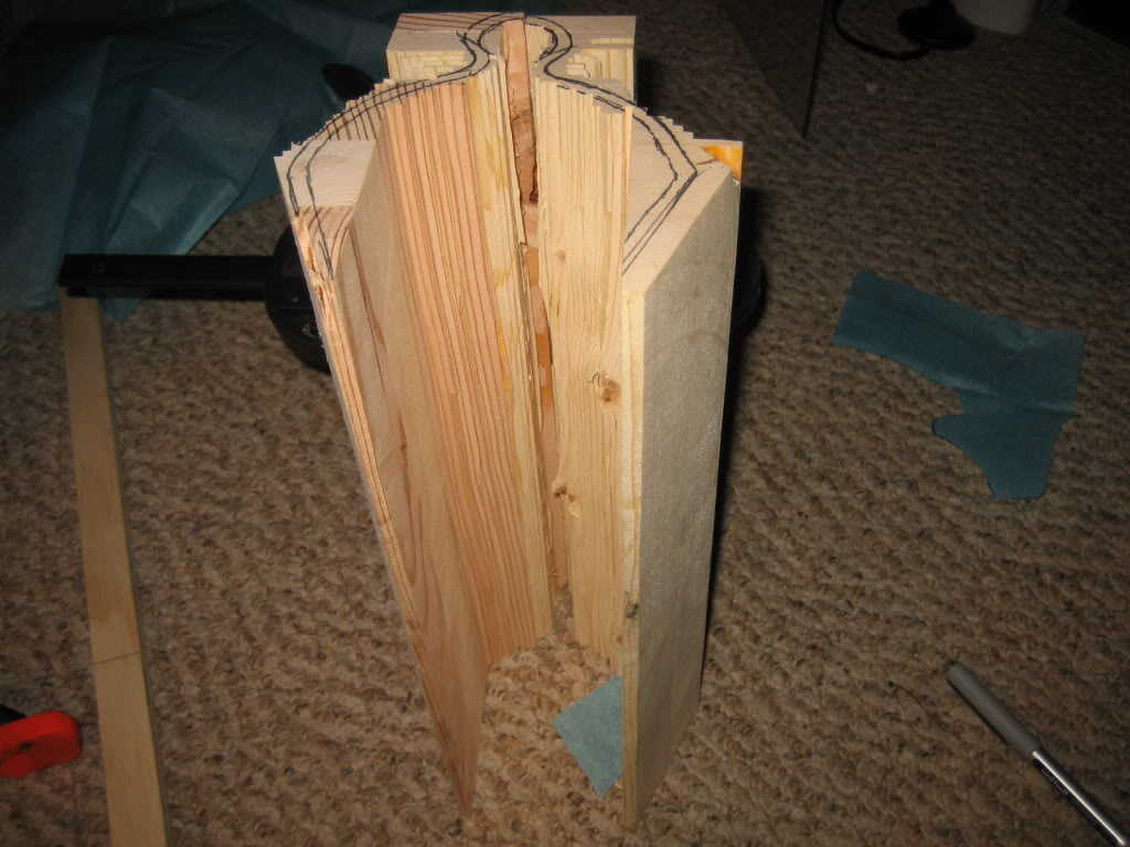
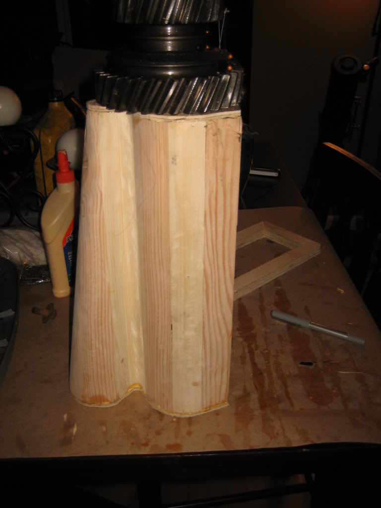
And, in this picture, you can see the reason for the seam in the middle:
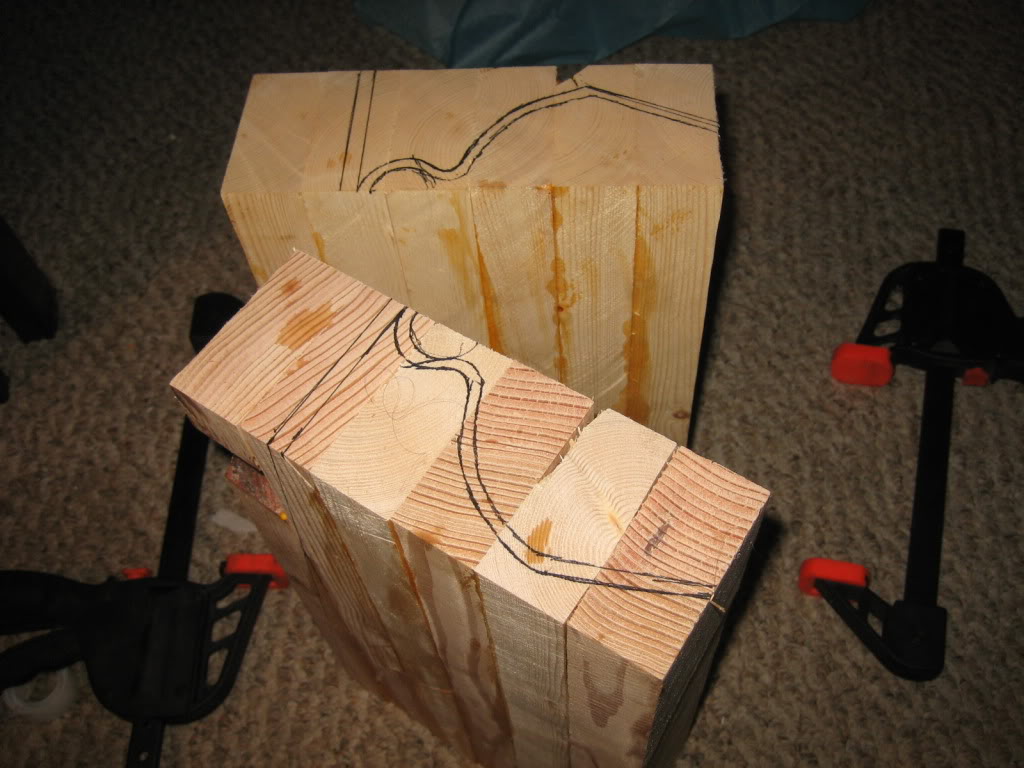
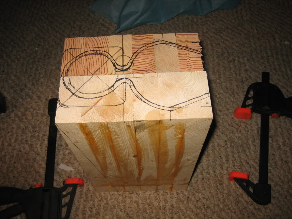
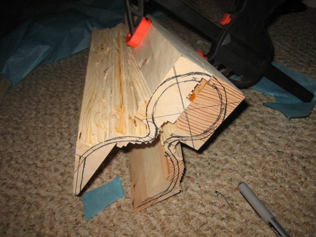
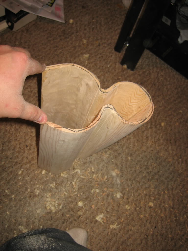
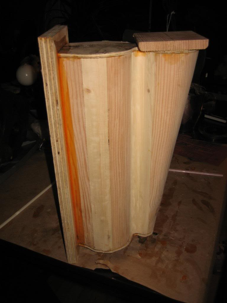
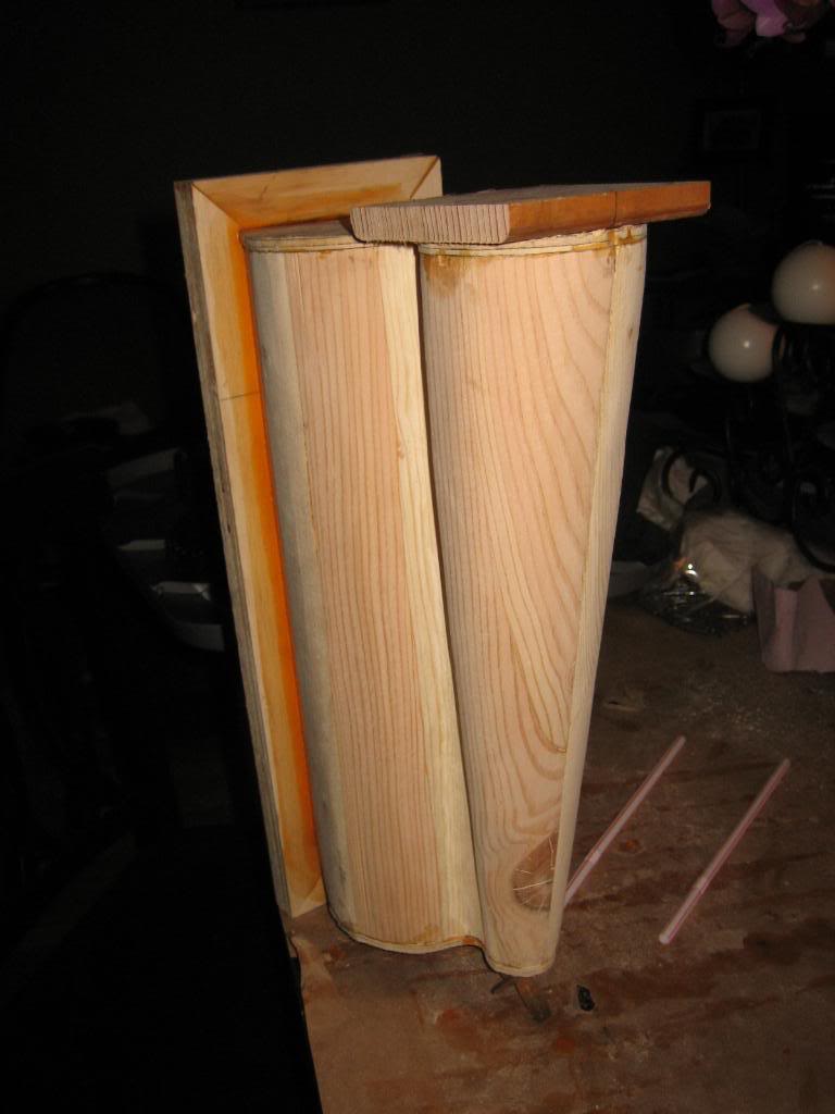
Next step was to trace and cut the taper on the Lehman Chamber:
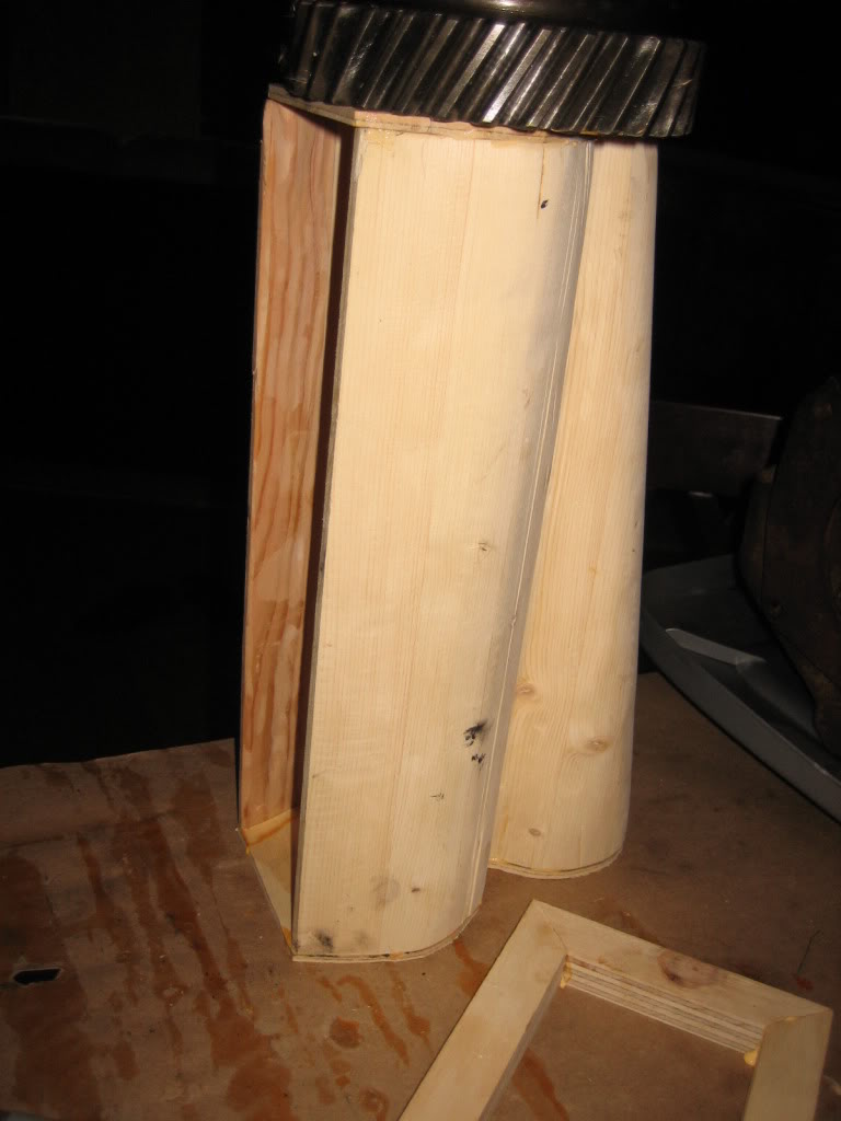
Then, deck the sides:
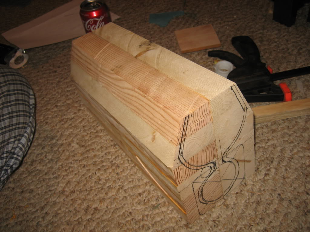
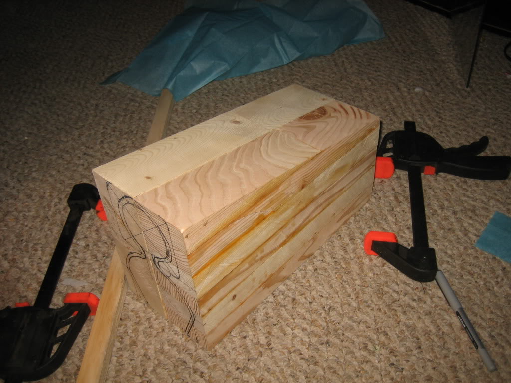
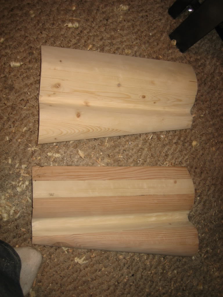
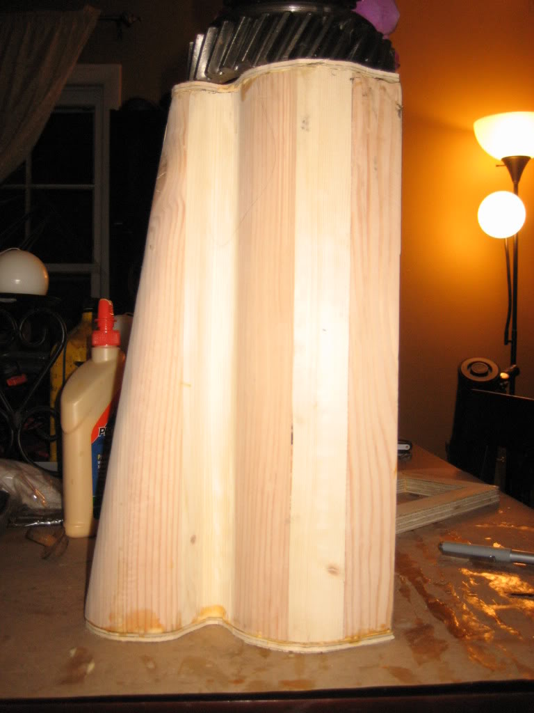
then, go wild with the table saw, and remove as much material as possible:
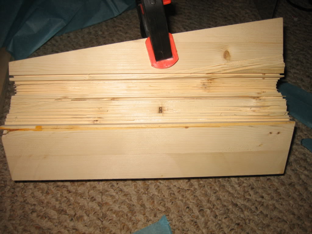
then, after making all these:
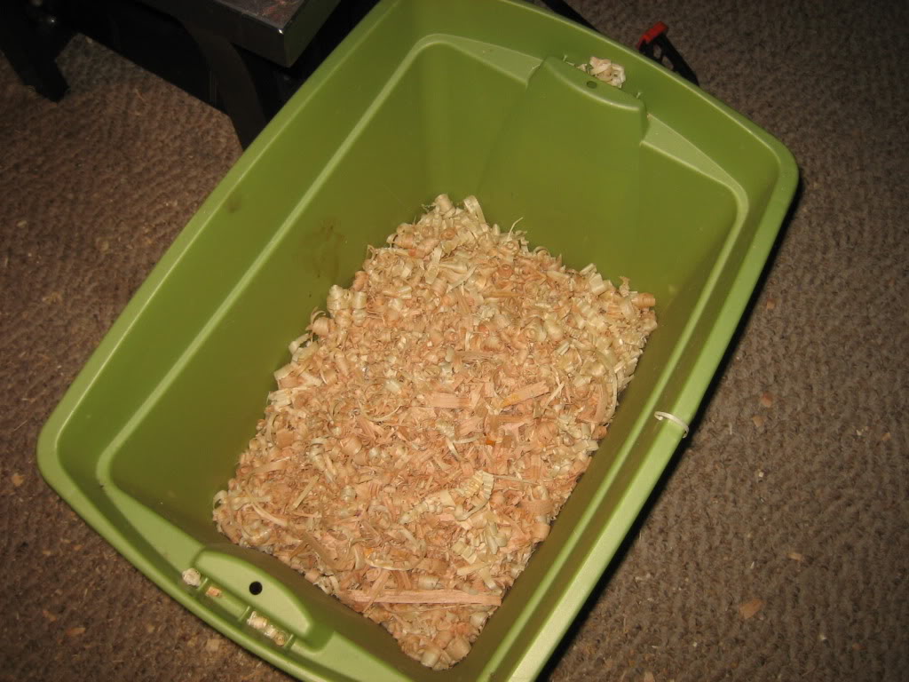
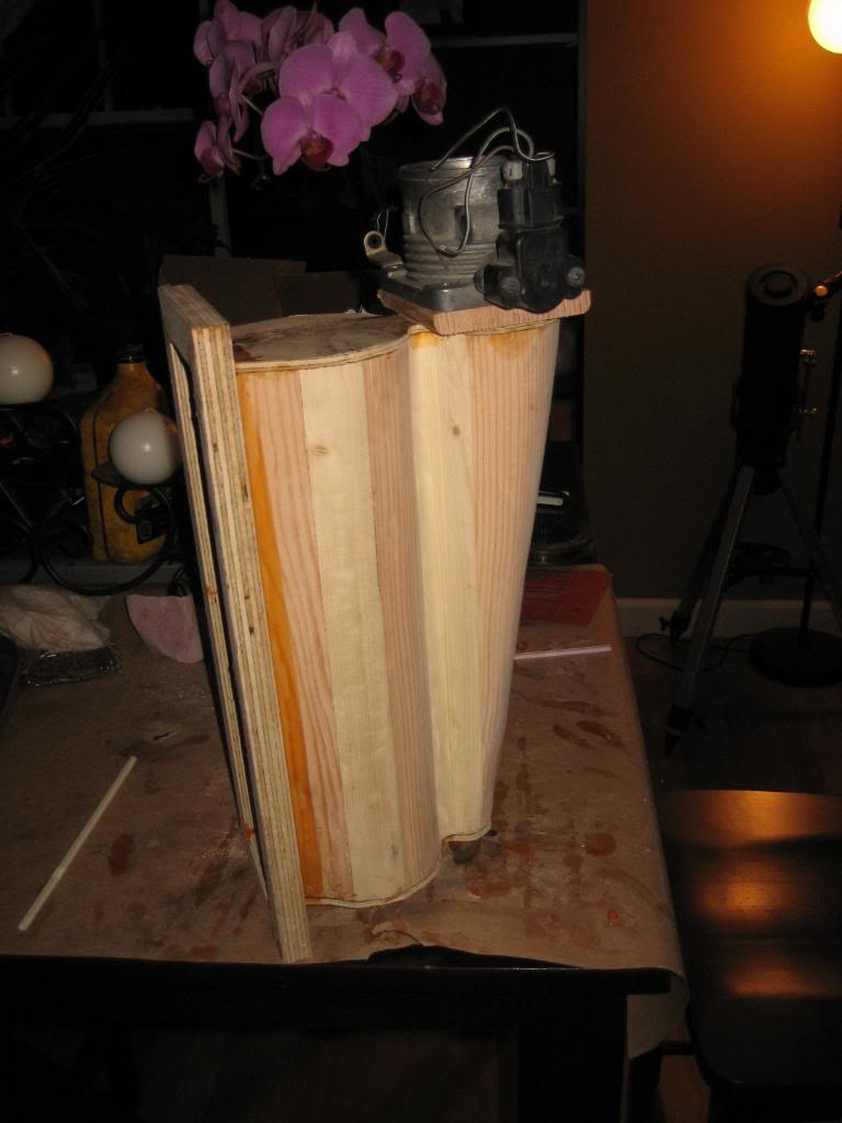
And some sanding (I got smart and put an 80 grit flapper wheel on my 4 1/2" grinder... made on heck of a mess, bet it cleaned it up fast, especially those pesky knots!)
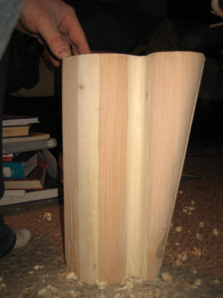
you get this:
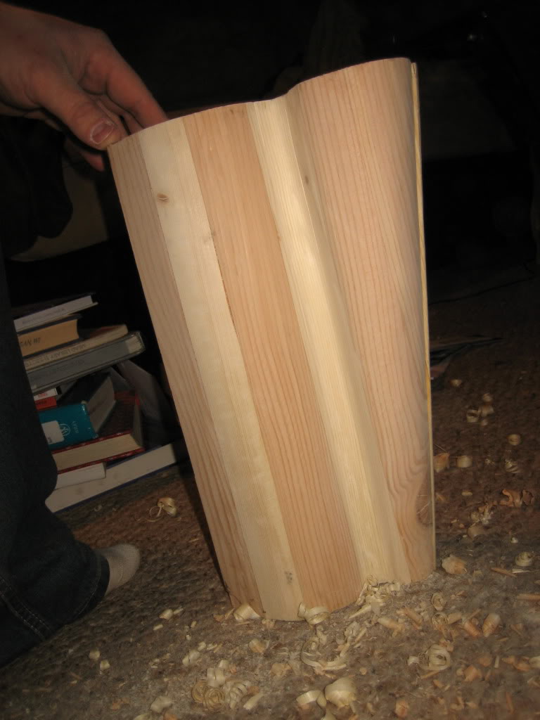
I like the candy stripe of the pine mixed with the red doug fir. I didnt do it on pupose, I just used what wood I had lying around
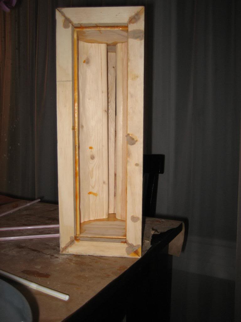
Then, ripped some 1/8" thick end plates oout of plywood on the tablesaw, and cut the profile on the scroll saw:
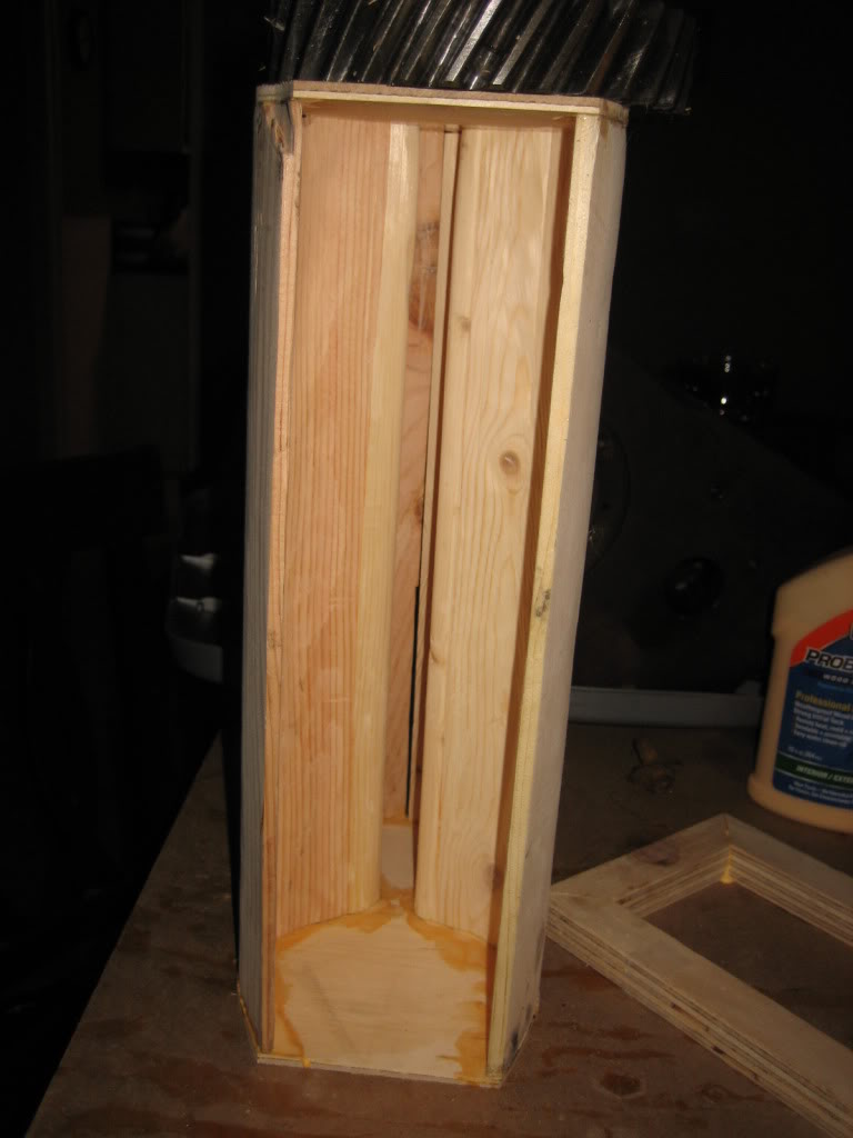
And, I'm going to make a slight tweak to the original design. In the original design, I had a slot taken out between the runners. Im going to try to avoid doing that, and, instead, make a steel backing plate that will gasket joint to the face of the plenum. Then, steel runners down to teh heads. This is for two reasons: 1. servicability. I can disassemble the entire unit then. And 2. vibration. Long curvy cast aluminum runners would be a pain to make, and would most likely crack from theweight of such a large plenum hanging off the end.
to do that, I of course need a gasket surface, and that is what this is for:
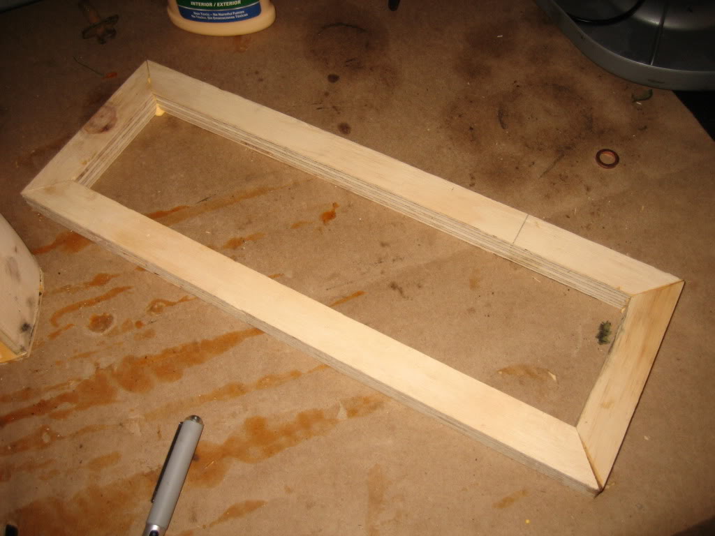
I'll glue that onto the wood model, so that I get a nice thick cast lip, then drill and tap that for bolts, and bolt the steel end plate to it. That 3/4" thick plywood, which will give me a good thick gasket surface I can machine flat and then drill and tap.
I rebuilt the steering box. was in desperate need of it. I also tapped the box for the power assist cylinder lines.
Also:
Redesigned my intake manifold, after reading this:
Turbo Intake Plenum - HybridZ
I plan on adding the fins through the slot, as he did, but, modeling them would have been a beast. I still haven't figured out how he did it, exactly!
I also have a trick up my sleeve on how I'm going to make them... you'll see further down.
One last addition is this, as well:
Laminova Production AB
They are VERY unique in how they function. A typical intercooler core relies on turbulent flow to get the most heat transfer, whereas with all the fins, a Laminova core is much, much more efficient due to the laminar flow of the air over the fins. I havent nailed down completely yet how I'm going to make them fit, but I've got a few ideas. Anyway, here are some pictures:
As you all can tell from the model, that is one hellaciously complicated hunk of modern art/intake plenum. As such, I know anything I try to weld up will look terrible
so.....
I'm going to cast them.
First step is to make a positive mold. After a bit of debating, I decided to do a wood mold, as I have a decent array of wood tools (another one of my hobbies) and A wood mold is infinately reusable, so long as I am gentle with it. This way, if I dont get the gating or risers right, I simple cast another plaster mold around my wooden model and keep pouring till I get it right.
So, I started out by ripping a 2X4 dow to 14" long chunks squared off at 1.5"X2.75".
I glued 6 of these together, then another 6 to form two 14"X6"X2.75" blocks. The seam in between them is not glued, and that is intentional, you'll see why in a bit.
I then traced the respective patterns on each end using dimensions from teh computer model. Unfortunately, I dont have a printer, otehrwise I would have just printed each end view, cut it out, and glued it on. For Throttle Bodies, I'm going to use a pair of ford 65mm Mustang 4.6L bodies I got at my local you pull it yard for $10 each. 65mm is 2.55 inches, perforct for the 2.5: discharge out of the Holset turbos.
TB end:
Opposite end:
And, in this picture, you can see the reason for the seam in the middle:
Next step was to trace and cut the taper on the Lehman Chamber:
Then, deck the sides:
then, go wild with the table saw, and remove as much material as possible:
then, after making all these:
And some sanding (I got smart and put an 80 grit flapper wheel on my 4 1/2" grinder... made on heck of a mess, bet it cleaned it up fast, especially those pesky knots!)
you get this:
I like the candy stripe of the pine mixed with the red doug fir. I didnt do it on pupose, I just used what wood I had lying around
Then, ripped some 1/8" thick end plates oout of plywood on the tablesaw, and cut the profile on the scroll saw:
And, I'm going to make a slight tweak to the original design. In the original design, I had a slot taken out between the runners. Im going to try to avoid doing that, and, instead, make a steel backing plate that will gasket joint to the face of the plenum. Then, steel runners down to teh heads. This is for two reasons: 1. servicability. I can disassemble the entire unit then. And 2. vibration. Long curvy cast aluminum runners would be a pain to make, and would most likely crack from theweight of such a large plenum hanging off the end.
to do that, I of course need a gasket surface, and that is what this is for:
I'll glue that onto the wood model, so that I get a nice thick cast lip, then drill and tap that for bolts, and bolt the steel end plate to it. That 3/4" thick plywood, which will give me a good thick gasket surface I can machine flat and then drill and tap.
 12-04-2009, 10:07 PM
#164
1.0 BAR
Thread Starter
Join Date: Feb 2003
Location: Wisconsin
Posts: 461
Time for an update!
So, I finished the pattern... and, it works!
I also did a 3D model of the runners and gates. I talked with a friend of mine at work, Jeremy, that works in our casting quality area, and he helped me develop the gates, runners, and gas tubes shown in the model.
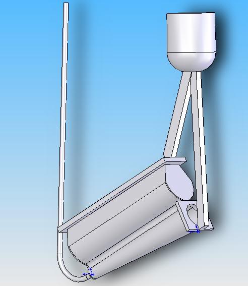
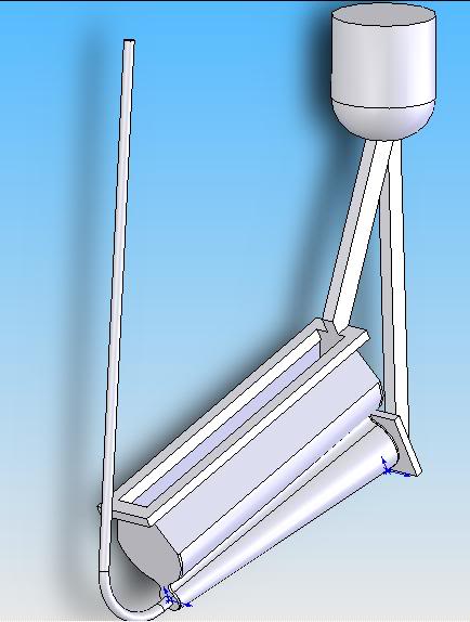
the long thin tube is a gas tube to allow the air to escape from the pattern as the metal is poured.
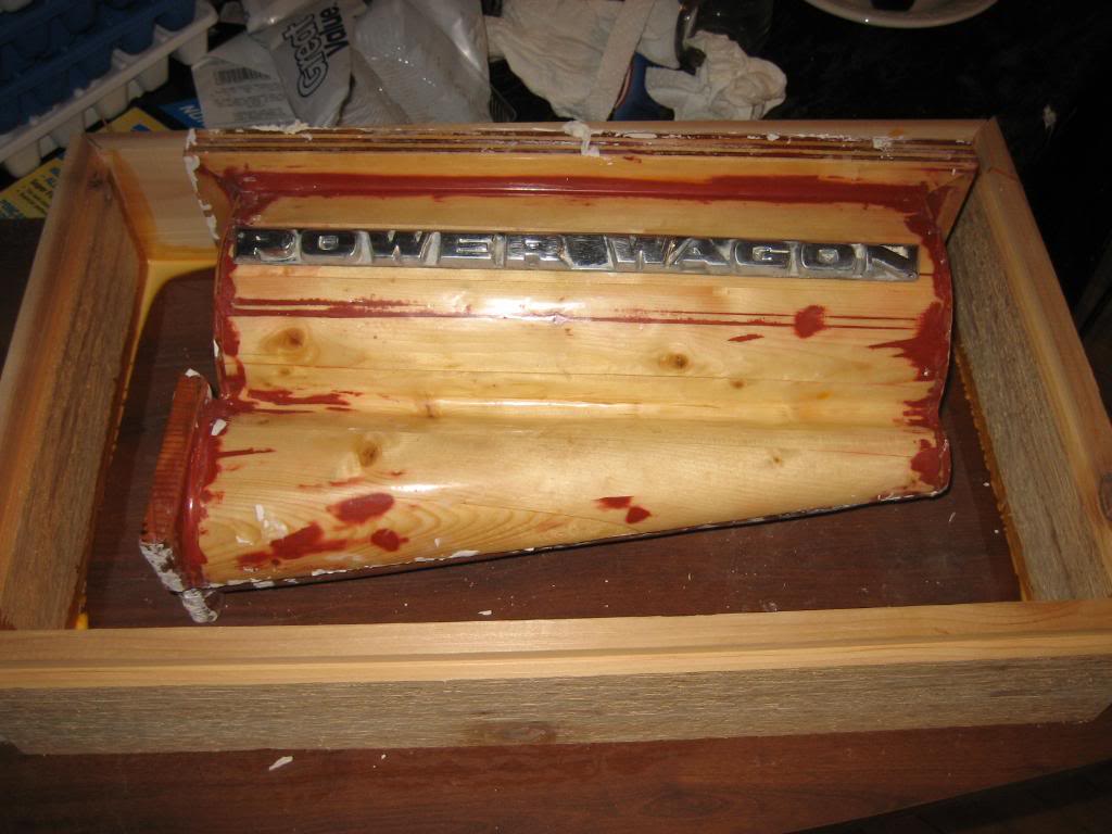
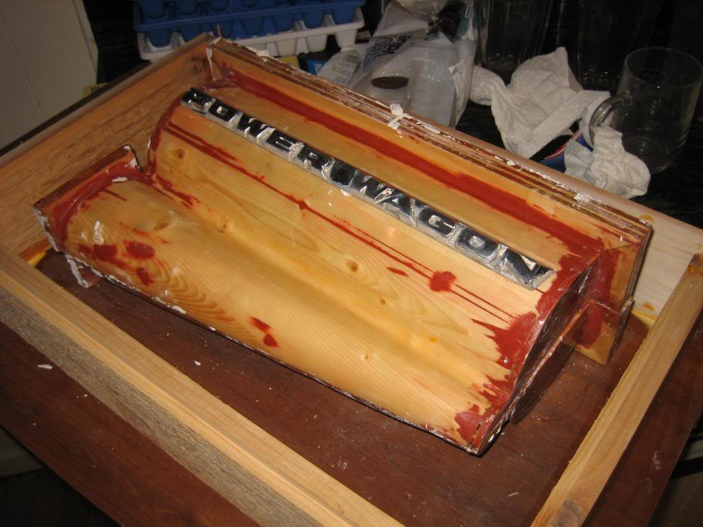
then, here is the pattern all glued together:
I didnt take any pictures of it, but, I went through and radiused a lot of the sharp edges with body filler, sanded out high spots, and filled low ones, then coated the whole thing in fiberglass resin to give it a smooth surface. I then sanded it out with fine sandpaper, and buffed it, so it was like glass to get the plaster to release.
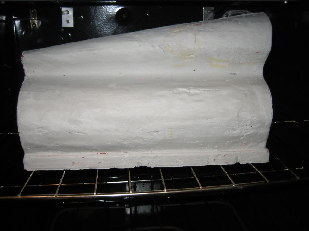
Speaking of, my 1st attempt:
not so good... not enough water.
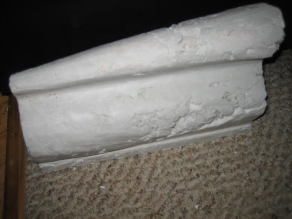
So, second attempt:
better, but, if you leave it hollow, the wals are too thin to support themselves trying to pry the mold off, and you end up breaking them, like this:

so, as they say, 3rd time is the charm!
about 30 lbs of plaster scrap... good thing the stuff is cheap!
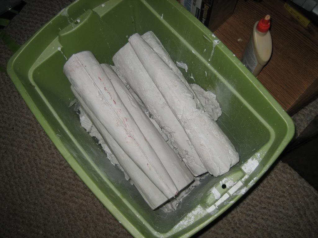
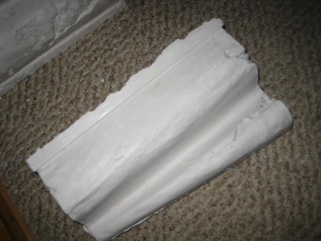
4th attempt was pretty good as well:

I need to fill a few spots where there were air bubbles, but overall, I am satisfied:
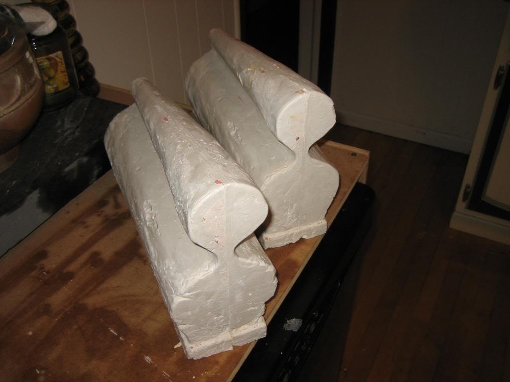
on to the outside... I had some scrap wood, so a whipped up this little box that will hold 1/2 the mold at a time. I made it kind of big... I might go back and fill some of it with foam blocks just to take up room so I need less plaster:
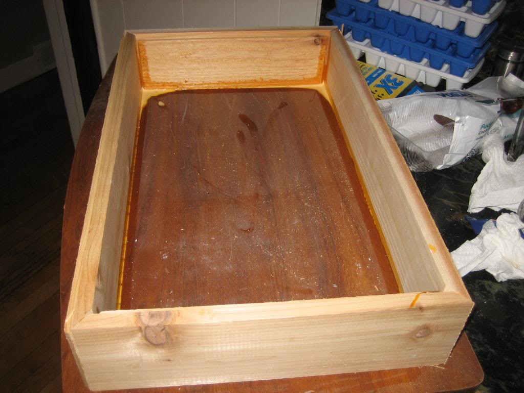
It won't get cored like this, this is both halves in at one time, but, it gives you an idea.. and yes, I'm going to attach the power wagon logo to the mold so that it will cast in the letters into the plenums :wink:
So, I finished the pattern... and, it works!
I also did a 3D model of the runners and gates. I talked with a friend of mine at work, Jeremy, that works in our casting quality area, and he helped me develop the gates, runners, and gas tubes shown in the model.
the long thin tube is a gas tube to allow the air to escape from the pattern as the metal is poured.
then, here is the pattern all glued together:
I didnt take any pictures of it, but, I went through and radiused a lot of the sharp edges with body filler, sanded out high spots, and filled low ones, then coated the whole thing in fiberglass resin to give it a smooth surface. I then sanded it out with fine sandpaper, and buffed it, so it was like glass to get the plaster to release.
Speaking of, my 1st attempt:
not so good... not enough water.
So, second attempt:
better, but, if you leave it hollow, the wals are too thin to support themselves trying to pry the mold off, and you end up breaking them, like this:
so, as they say, 3rd time is the charm!
about 30 lbs of plaster scrap... good thing the stuff is cheap!
4th attempt was pretty good as well:
I need to fill a few spots where there were air bubbles, but overall, I am satisfied:
on to the outside... I had some scrap wood, so a whipped up this little box that will hold 1/2 the mold at a time. I made it kind of big... I might go back and fill some of it with foam blocks just to take up room so I need less plaster:
It won't get cored like this, this is both halves in at one time, but, it gives you an idea.. and yes, I'm going to attach the power wagon logo to the mold so that it will cast in the letters into the plenums :wink:
 01-09-2010, 02:44 PM
#166
1.0 BAR
Thread Starter
Join Date: Feb 2003
Location: Wisconsin
Posts: 461
so, time for an update...
I picked up a pair of ladies the other day:
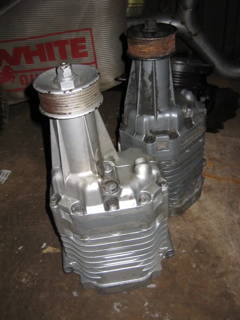
The superchargers are, of course, driven off the crank. I calculated the belt loading and such for the pair of blowers, and need a 1.5:1 ratio to give me 5 PSI of blower boost over atmospheric, or, a pressure ratio of 1.35.
That may not sound like much, but, with compound boost, the ratios are multiplied not added, so, if I run 10 PSI off the turbos, or, a pressur ratio of 1.7, I dont end up with 15 PSI of boost, I end up with 19 PSI of boost. It's important to let the turbos do most of the work, as the blowers are not as efficient, and, the point of the blowers is more to scavenge the cylinders than provide high boost.
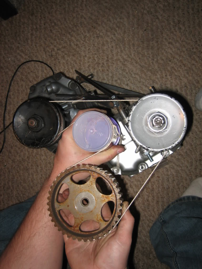
The good news in all this is a co-worker of mine has an 8 rib 4.75" pulley, wich will give me a 1.47:1 drive ratio with the pulleys that are on the fronts of the blowers now, so, I've got my serp pulley setup nailed down. The problem is the crank pulley, and the fact that the blowers are too short to reach out past the end of the waterpump, AND, my AC air pump is alsoin going to be in the way, so, to get past all that, I plan to run a jackshaft. I'll have the crank turn a cog belt belt, which will turn one end of the jackshaft. The other end will have the serp belt and the 4.75" pulley. To get the cog belt and cog pulleys, I went out to the junkyard I scrounge and found a smucked Ford contour with the 2.0 DOHC Zetec. I snagged both cam cogs for the timing belt, then took the factory front pulley off the 400 and made some solid models in solidworks. I cooked up this assembly:
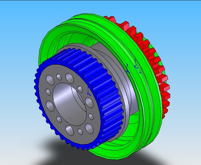
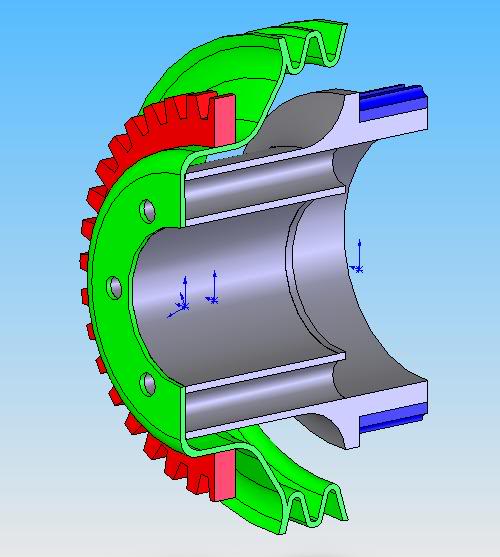
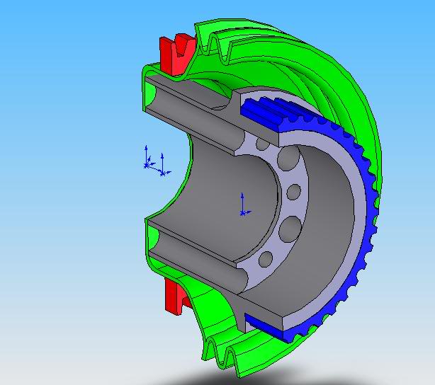
Green pulley is the stock 400 pulley. The red ring is the 36-1 toothed ring I'm going to use for the EFI to keep track of RPM and crank position. Grey hub is the part I need to have made, and the blue ring is the outside of one of the Zetec pulleys. I'll have a local shop make the adapter, and then machine the Zetec pulley for a light press fit, same with the red 36-1 ring.

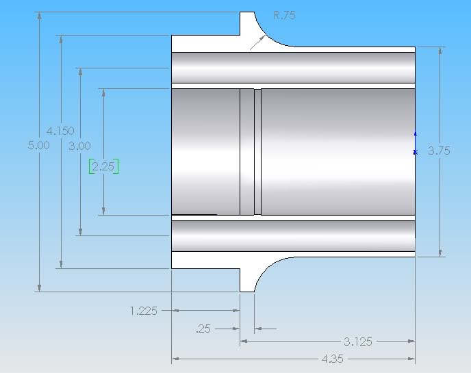
hub will me made from aluminum. The 6 large holes are just to remove weight, while the 6 smaller ones will bolt it to the crank. The large hole in the middle is both to remove weight, as well as clear the stock crank snout bolt. The inner diameter will pilot on the crank snout, keeping it all concentric. I did the mass calculations in soldworks and it will weigh about 2.3 lbs.
And, a few cutaways showing the assembly:
I picked up a pair of ladies the other day:
The superchargers are, of course, driven off the crank. I calculated the belt loading and such for the pair of blowers, and need a 1.5:1 ratio to give me 5 PSI of blower boost over atmospheric, or, a pressure ratio of 1.35.
That may not sound like much, but, with compound boost, the ratios are multiplied not added, so, if I run 10 PSI off the turbos, or, a pressur ratio of 1.7, I dont end up with 15 PSI of boost, I end up with 19 PSI of boost. It's important to let the turbos do most of the work, as the blowers are not as efficient, and, the point of the blowers is more to scavenge the cylinders than provide high boost.
The good news in all this is a co-worker of mine has an 8 rib 4.75" pulley, wich will give me a 1.47:1 drive ratio with the pulleys that are on the fronts of the blowers now, so, I've got my serp pulley setup nailed down. The problem is the crank pulley, and the fact that the blowers are too short to reach out past the end of the waterpump, AND, my AC air pump is alsoin going to be in the way, so, to get past all that, I plan to run a jackshaft. I'll have the crank turn a cog belt belt, which will turn one end of the jackshaft. The other end will have the serp belt and the 4.75" pulley. To get the cog belt and cog pulleys, I went out to the junkyard I scrounge and found a smucked Ford contour with the 2.0 DOHC Zetec. I snagged both cam cogs for the timing belt, then took the factory front pulley off the 400 and made some solid models in solidworks. I cooked up this assembly:
Green pulley is the stock 400 pulley. The red ring is the 36-1 toothed ring I'm going to use for the EFI to keep track of RPM and crank position. Grey hub is the part I need to have made, and the blue ring is the outside of one of the Zetec pulleys. I'll have a local shop make the adapter, and then machine the Zetec pulley for a light press fit, same with the red 36-1 ring.
hub will me made from aluminum. The 6 large holes are just to remove weight, while the 6 smaller ones will bolt it to the crank. The large hole in the middle is both to remove weight, as well as clear the stock crank snout bolt. The inner diameter will pilot on the crank snout, keeping it all concentric. I did the mass calculations in soldworks and it will weigh about 2.3 lbs.
And, a few cutaways showing the assembly:
01-09-2010, 09:48 PM
#167
1.0 BAR
Thread Starter
Join Date: Feb 2003
Location: Wisconsin
Posts: 461
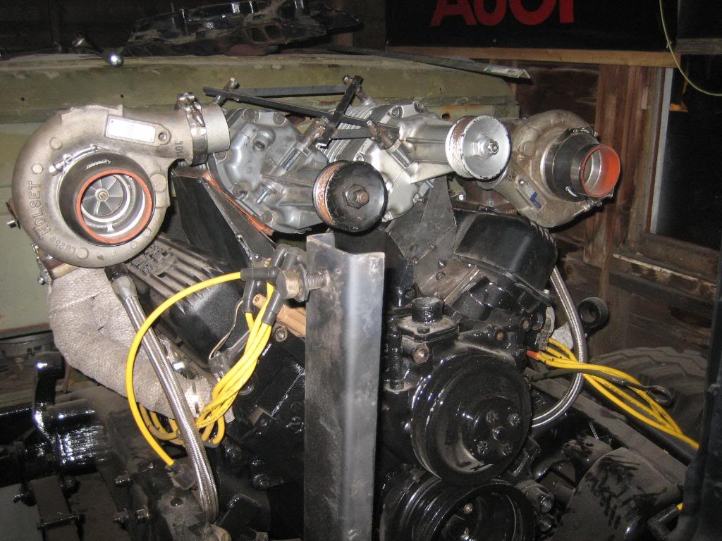
made a jig to hold the blowers in alignment, then worked on the serp belt routing. Came up with a BEAUTIFUL routing that has over 180* of wrap on the drive and second blower, and 180* on the first blower, along with a single idler that will be loaded with an autotensioner arm. Simple, elegant, and should be effective. The "Vee" between the two blowers will also still give me a good spot to route the turbo inlet pipe in from the air cleaner on the fender. Now, I just have to design the manifolds that connec the blowers to the heads:
 01-16-2010, 07:56 PM
#169
1.0 BAR
Thread Starter
Join Date: Feb 2003
Location: Wisconsin
Posts: 461
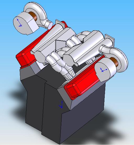
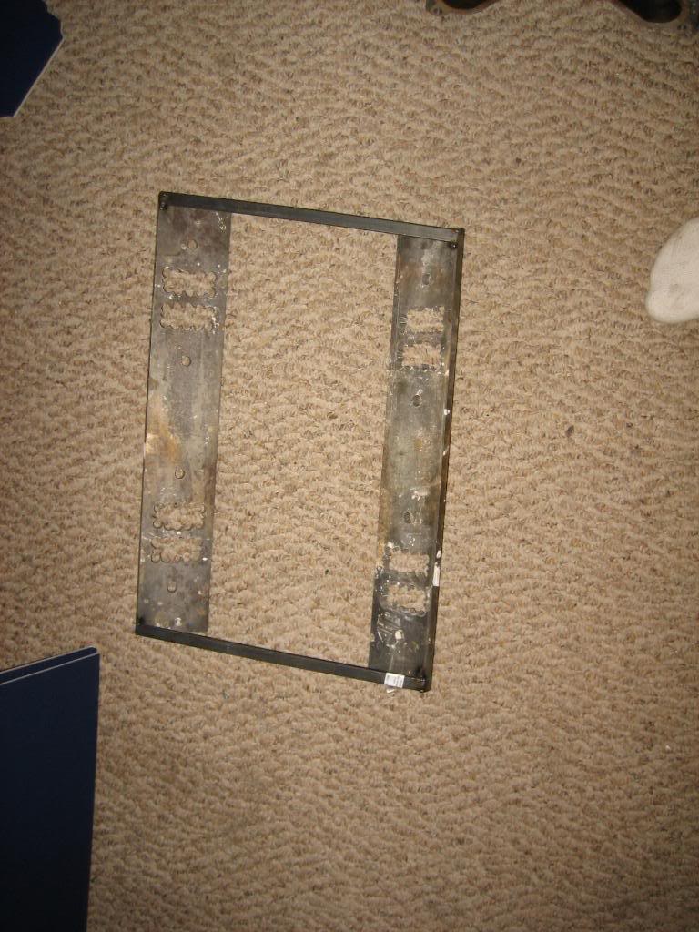
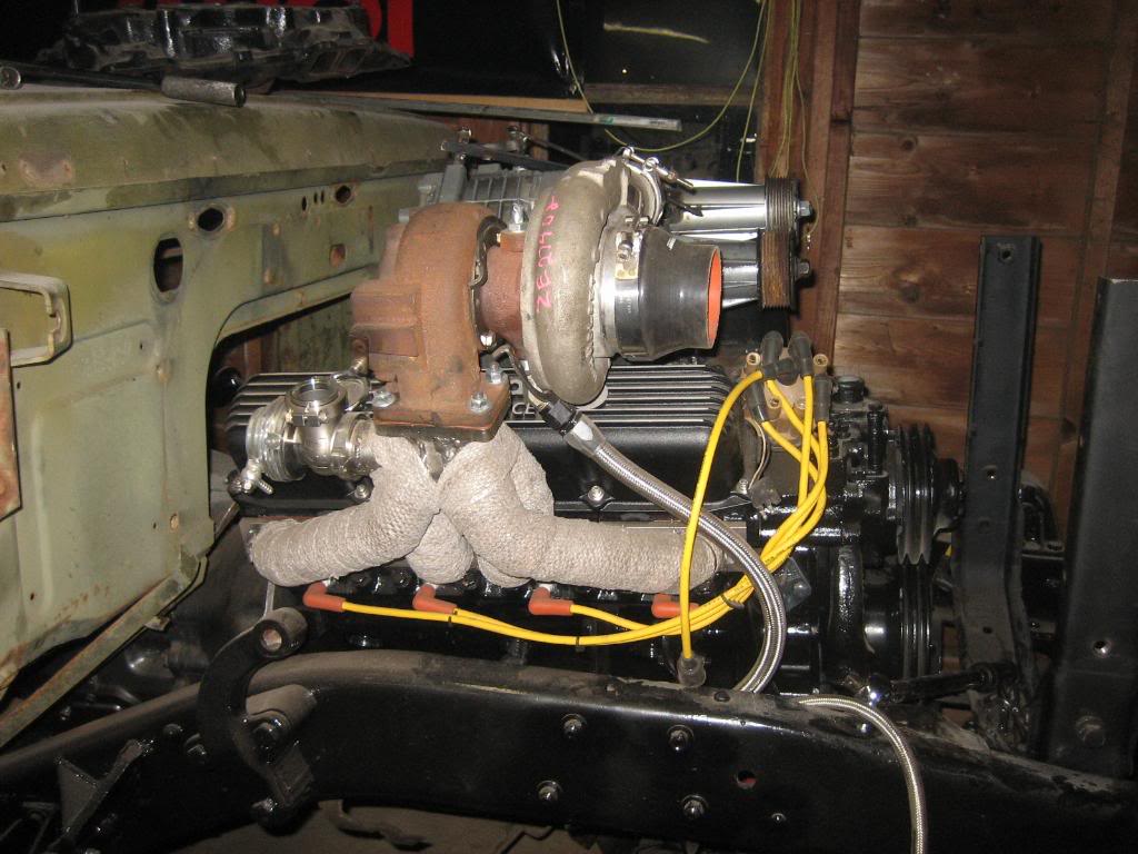
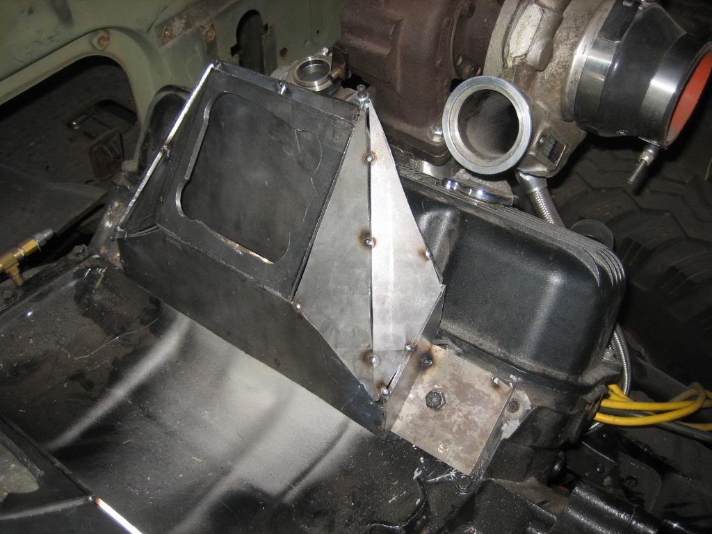
Been playing with multiple different mounting orientations and came up with the determination that my original plan of a 90* "V" would be the best. I made two 3/8" thick head plates. They need to be finished out yet, but they are close enough for now, and I welded spacers in to hold the distanc between the heads.
I then squared up the flanges to the blowers, and mocked up the plenums using foamboard:
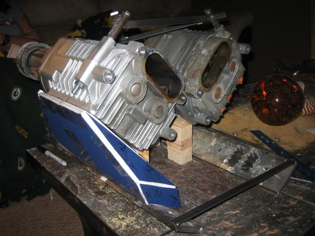

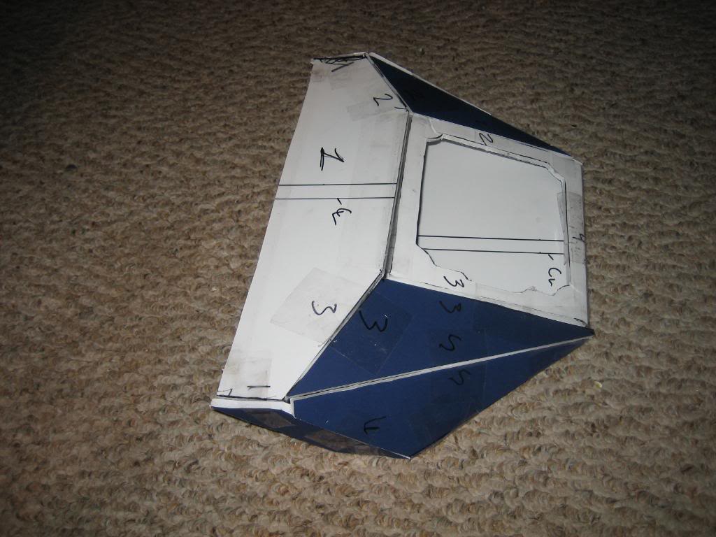

I then cut the parts out of 1/8" steel plate, as the boost pressure could be as high as 20 PSI when I am done, and the long side by the valve cover has a surface area of about 65 square inches, and at 20 PSI there would 1300 lbs of force trying to bend that plate! :shock:
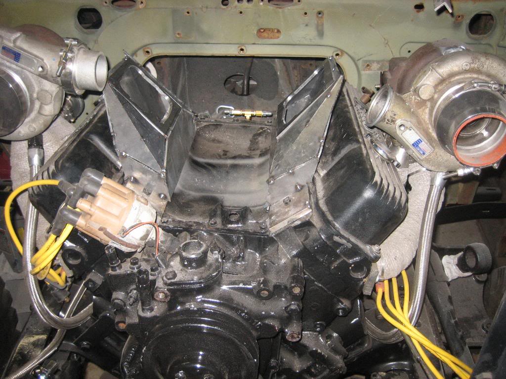
I tacked them all together, and then test fit on the engine. I need to break a few tacks and make some adjustments, but, it is 90% there.
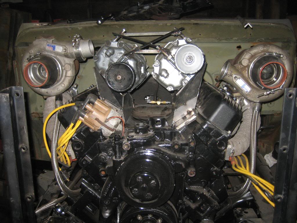
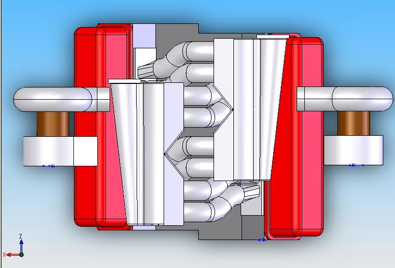
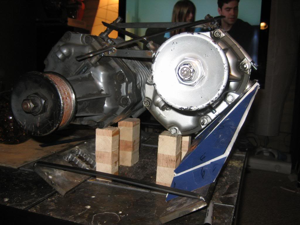
I then bought the factory supercoupe jackshaft pulleys and mounts and tensioner from one of my coworkers, and he gave me an old belt to try the mockup with:
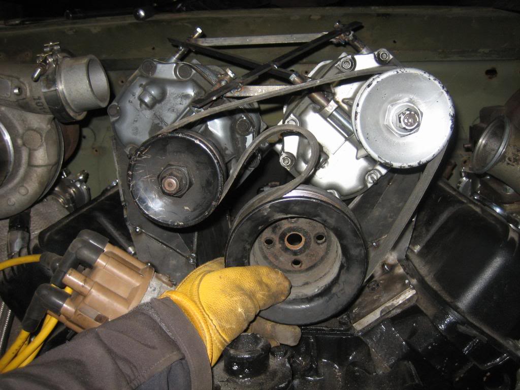
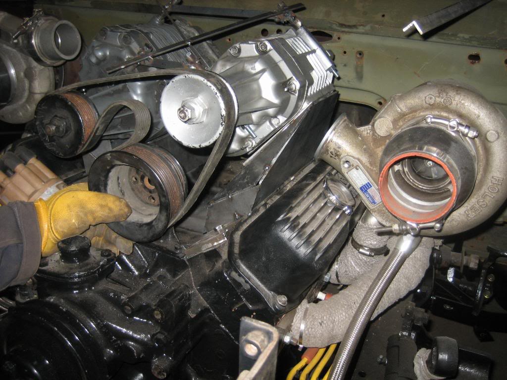
looks very promising. I might need a hair longer belt, but it is close.
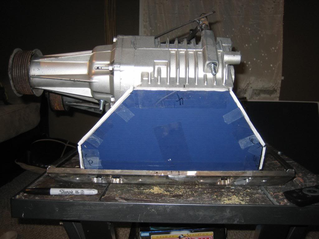
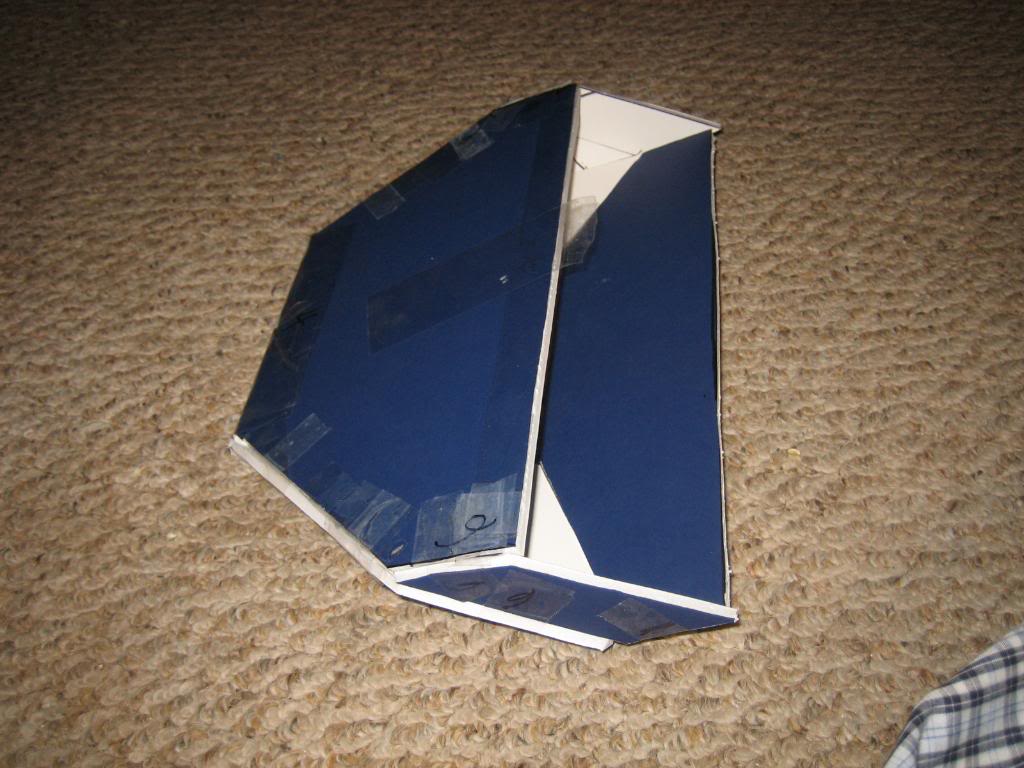
then, a few pictures of the plenums without the blowers sitting on top:
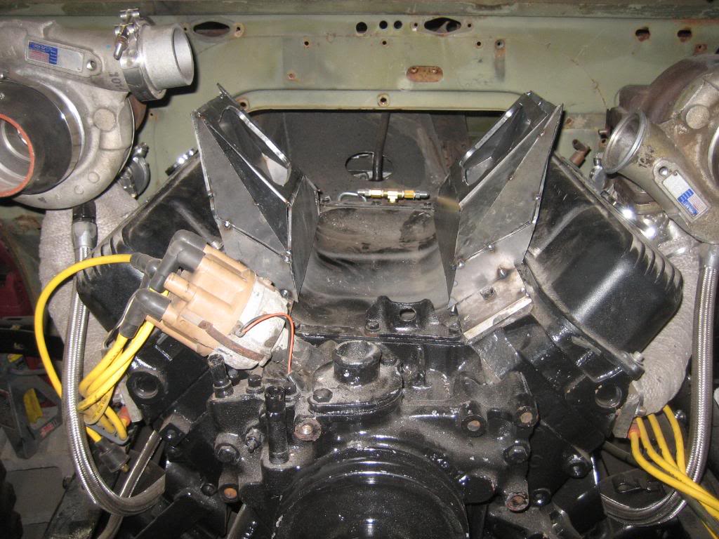
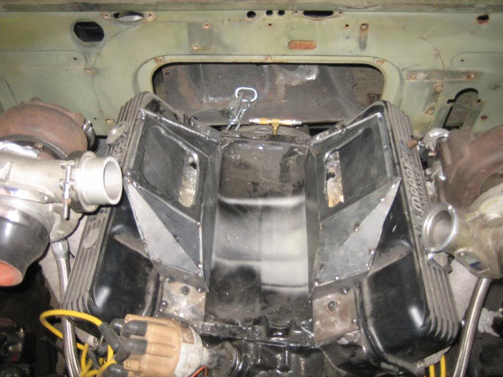
I'm sure you are wondering how I plan to attahc the blowers. I'm going to drill holes through the mounting flange, and through the sidewals of the plenum boxes, and weld in compression sleeves. The bolts will pass through the sleeves, and thread into the blowers.
I'll mount my injectors down between the plenums, at a 90* angle to the inside wall. They will be nice and hidden, giving it a clean look. I'll also need to weld in a balance tube between the blowers to balance the vacuum signal between the banks. Finally, I'm going to make two plates, once the blowers are hard mounted to the plenums. One at the front, coming off the 4 bolts of the blower case closest to the V, and one across the back, to hold alignment between the blowers, and prevent them from ------ing. Finally, I'll make a jackshaft bearing mount on the front to support one end of the jackshaft and autotensioner pulley, and a second mount on the front of the water pump for the other end with the cog belt. I printed off my hub plans, and dropped them off at a local machine shop, I should get a quote back on it sometime next week.
I then squared up the flanges to the blowers, and mocked up the plenums using foamboard:
I then cut the parts out of 1/8" steel plate, as the boost pressure could be as high as 20 PSI when I am done, and the long side by the valve cover has a surface area of about 65 square inches, and at 20 PSI there would 1300 lbs of force trying to bend that plate! :shock:
I tacked them all together, and then test fit on the engine. I need to break a few tacks and make some adjustments, but, it is 90% there.
I then bought the factory supercoupe jackshaft pulleys and mounts and tensioner from one of my coworkers, and he gave me an old belt to try the mockup with:
looks very promising. I might need a hair longer belt, but it is close.
then, a few pictures of the plenums without the blowers sitting on top:
I'm sure you are wondering how I plan to attahc the blowers. I'm going to drill holes through the mounting flange, and through the sidewals of the plenum boxes, and weld in compression sleeves. The bolts will pass through the sleeves, and thread into the blowers.
I'll mount my injectors down between the plenums, at a 90* angle to the inside wall. They will be nice and hidden, giving it a clean look. I'll also need to weld in a balance tube between the blowers to balance the vacuum signal between the banks. Finally, I'm going to make two plates, once the blowers are hard mounted to the plenums. One at the front, coming off the 4 bolts of the blower case closest to the V, and one across the back, to hold alignment between the blowers, and prevent them from ------ing. Finally, I'll make a jackshaft bearing mount on the front to support one end of the jackshaft and autotensioner pulley, and a second mount on the front of the water pump for the other end with the cog belt. I printed off my hub plans, and dropped them off at a local machine shop, I should get a quote back on it sometime next week.

 But i cant see why you wanna 2 superchargers also? Should'nt the 2 turbos be more than capable to produce the horsepower you want?


