Power Wagon Rebuild (Update: 11/5/08)


 05-26-2009, 09:01 PM
#105
1.0 BAR
Thread Starter

Join Date: Feb 2003
Location: Wisconsin
Posts: 461
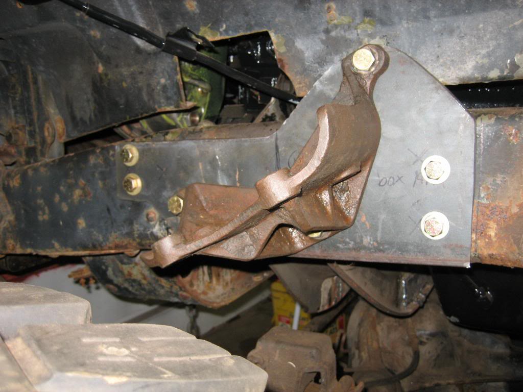
Got some more work done. I dont know how many of you remember my earlier comments about the difficulty of mounting the steering box, as the steering box and new motor mount crossmember want to occupy the same area of frame real estate. Even if I could get it to fit, I wasnt too wild about drilling all those holes in the frame without any kind of reinforcement, but, I came up with the perfect solution:
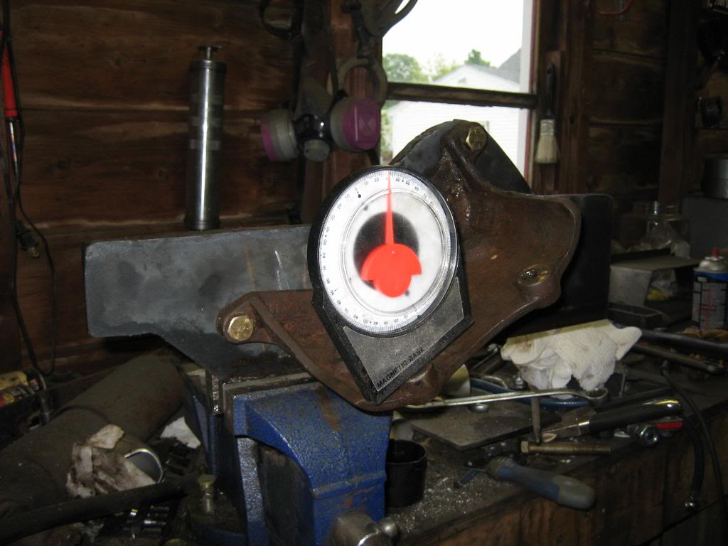
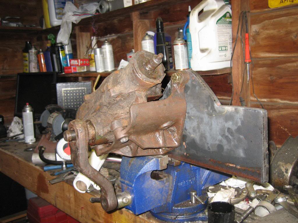
That's a chunk of 1/2" thick steel... the bracket is sitting at a 25* angle from the 4 mounting pads for the steering box from horizontal. I found the angle by putting the steering box on my vise, shimming it to level it, then, putting my angle finder on the pitman arm, and cycling it through it's travel. I came up with 25* angle from horizontal.
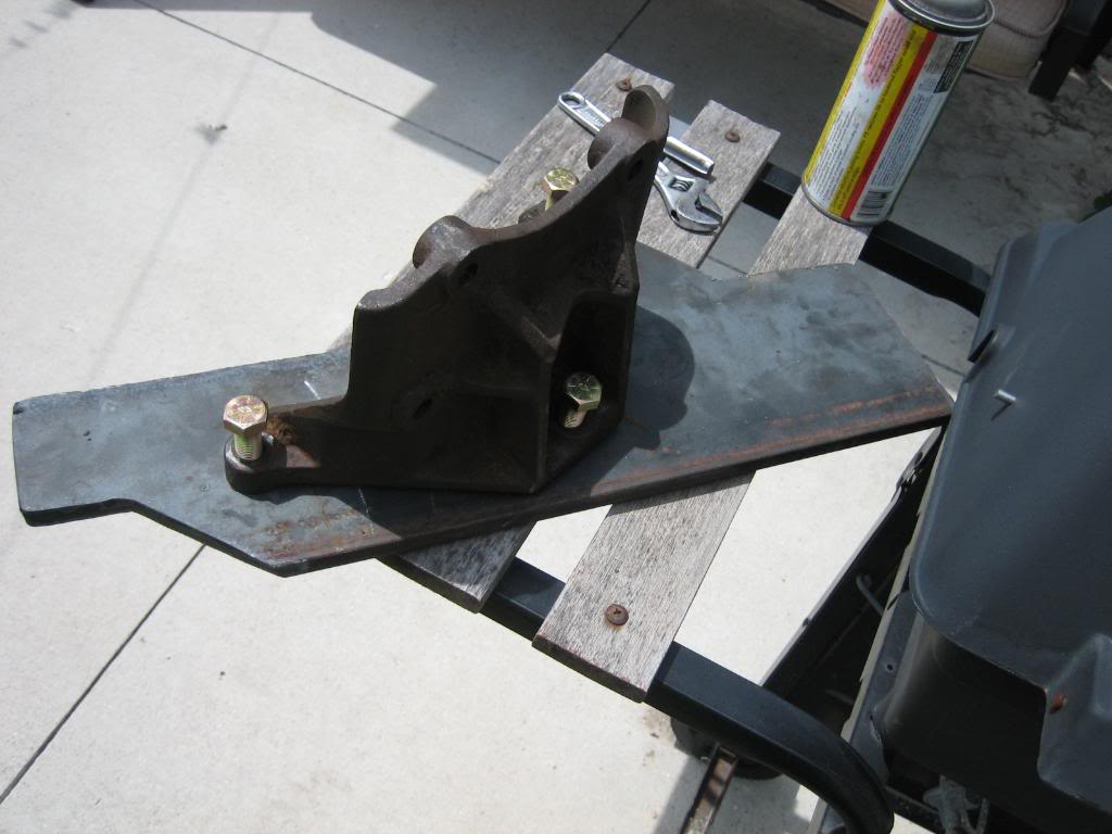
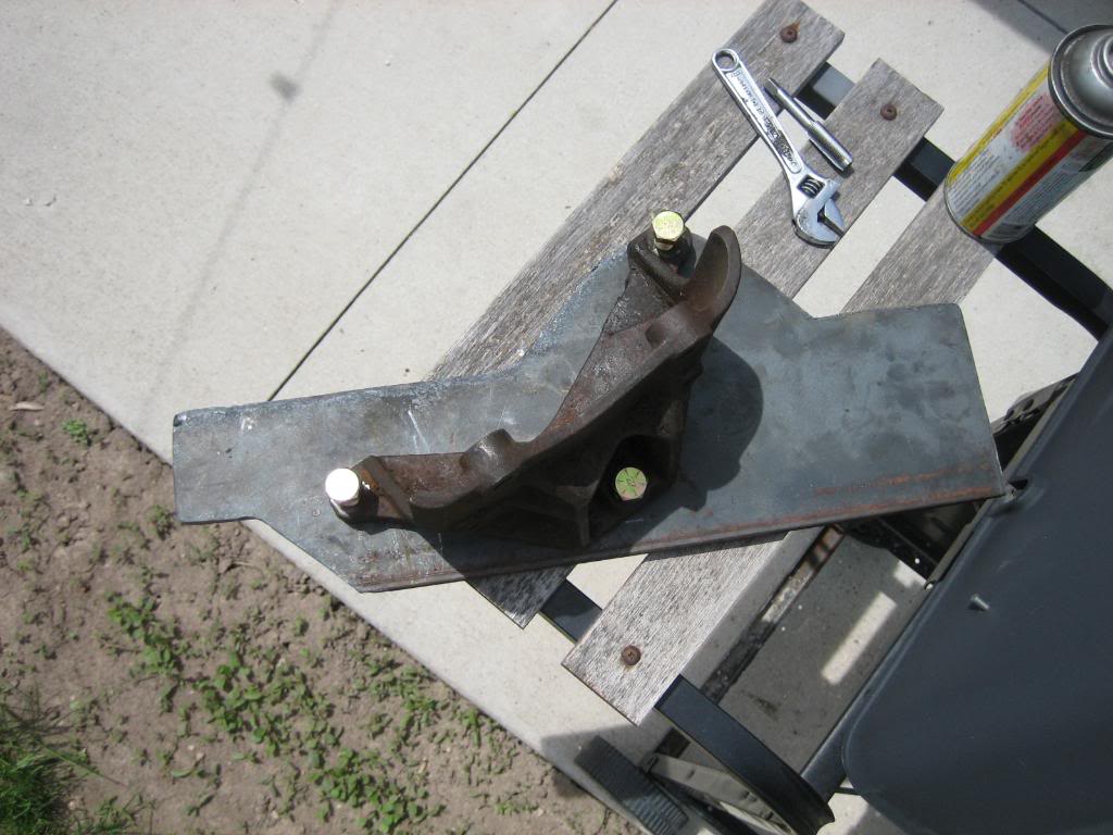
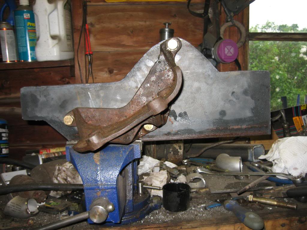
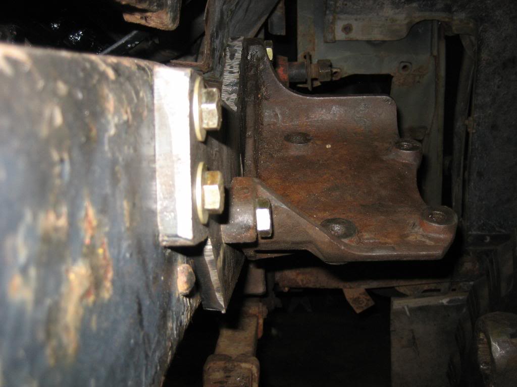
I then drilled and tapped the 1/2" plate for the 3 1/2" holes. I used fine thread so that I had 10 turns of contact. I then ground the two lower bolts off flush with the plate on the back side:
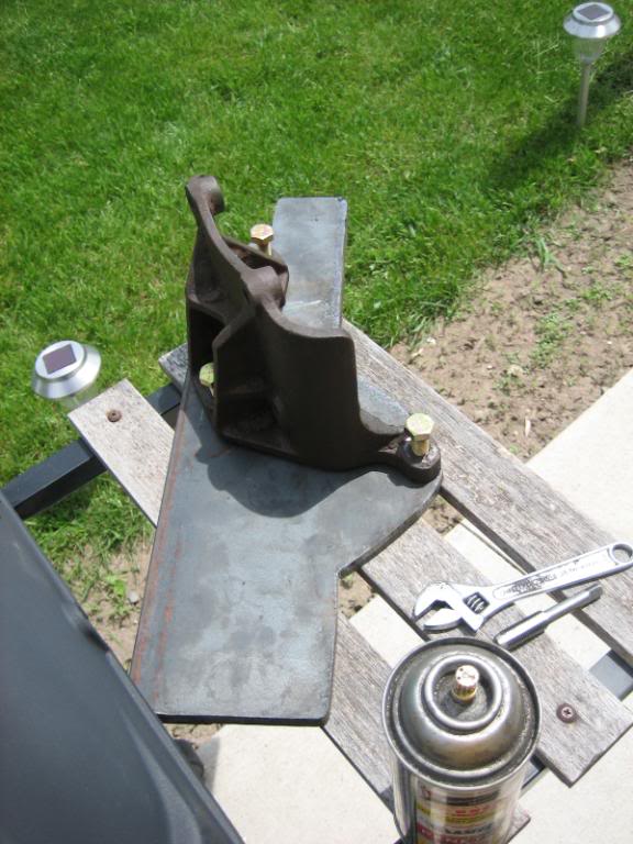
Checking the angle:
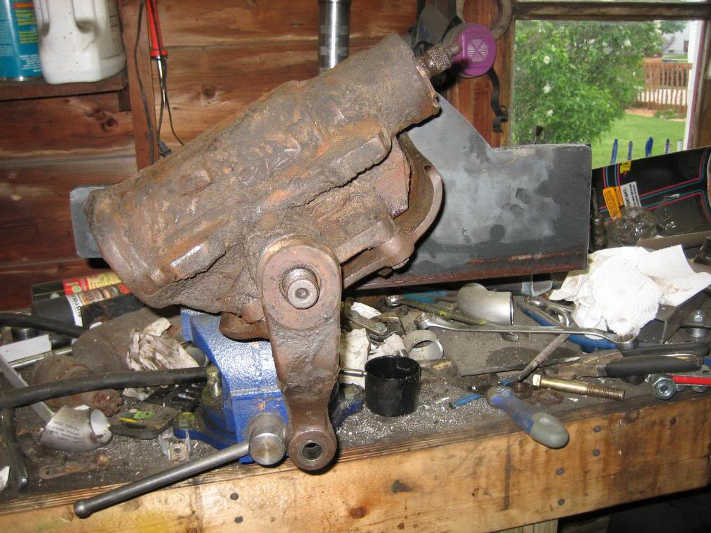
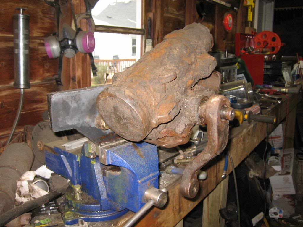
Steering box test fit:
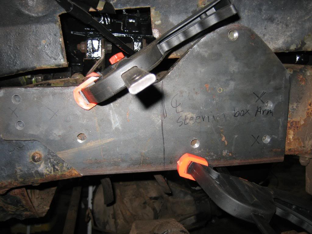
Now, I'm sure at this point, you're thinking "jeepers, why not just through bolt it to the frame" And, here in lies the slick part of this setup... The steering box is going to sit right over where the 4 bolts for the motor mount go, so, I bolt that plate to the frame, then, drill and tap it from the inside, for the 4 motor mount bolts, so that they dont run into the steering box... I got 4 7/16" fine thread bolts for the motor mount. Below is the test fit of the plate to the frame:
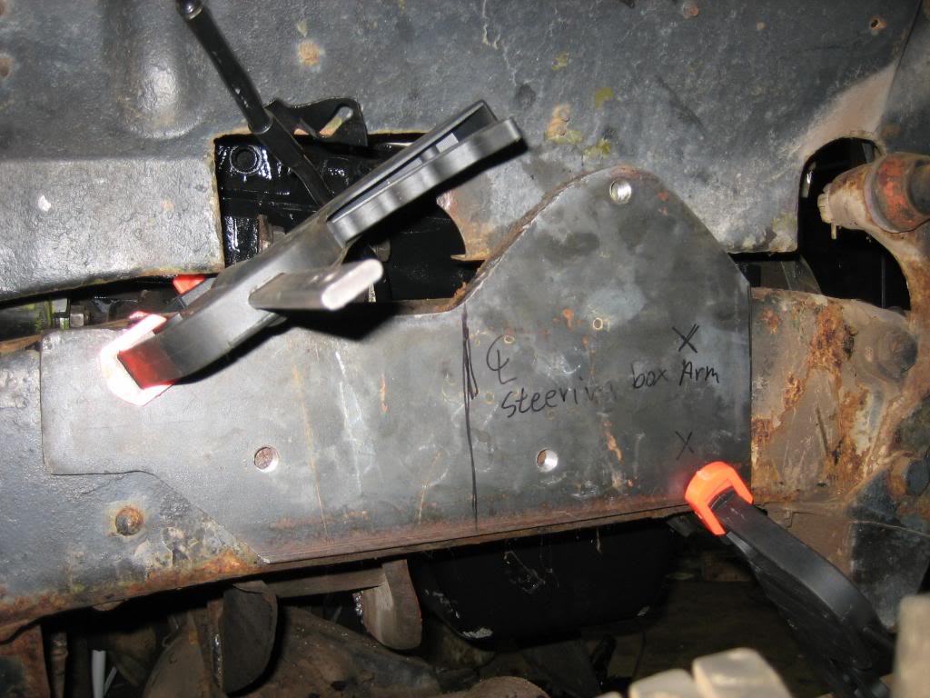
and, drilled the plate for the outer set of retaining bolts. Notice the engine mount through the hole in the splash shield, so, you get an idea of how the engine is going to bolt to the plate from the inside. These through bolt:
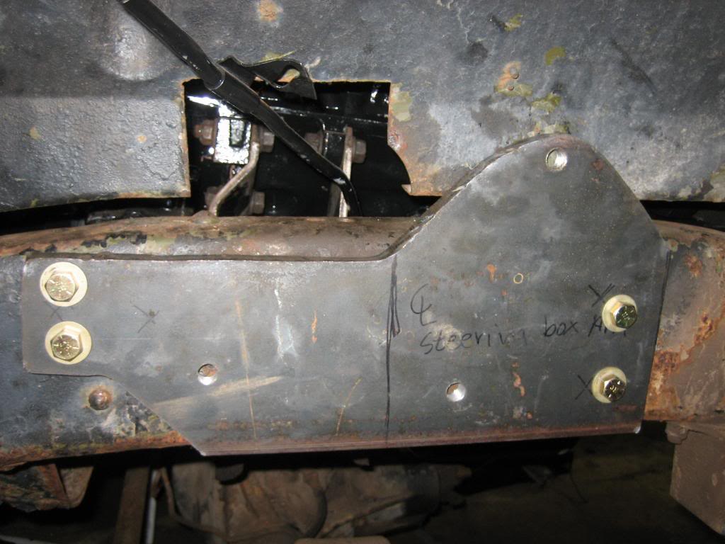
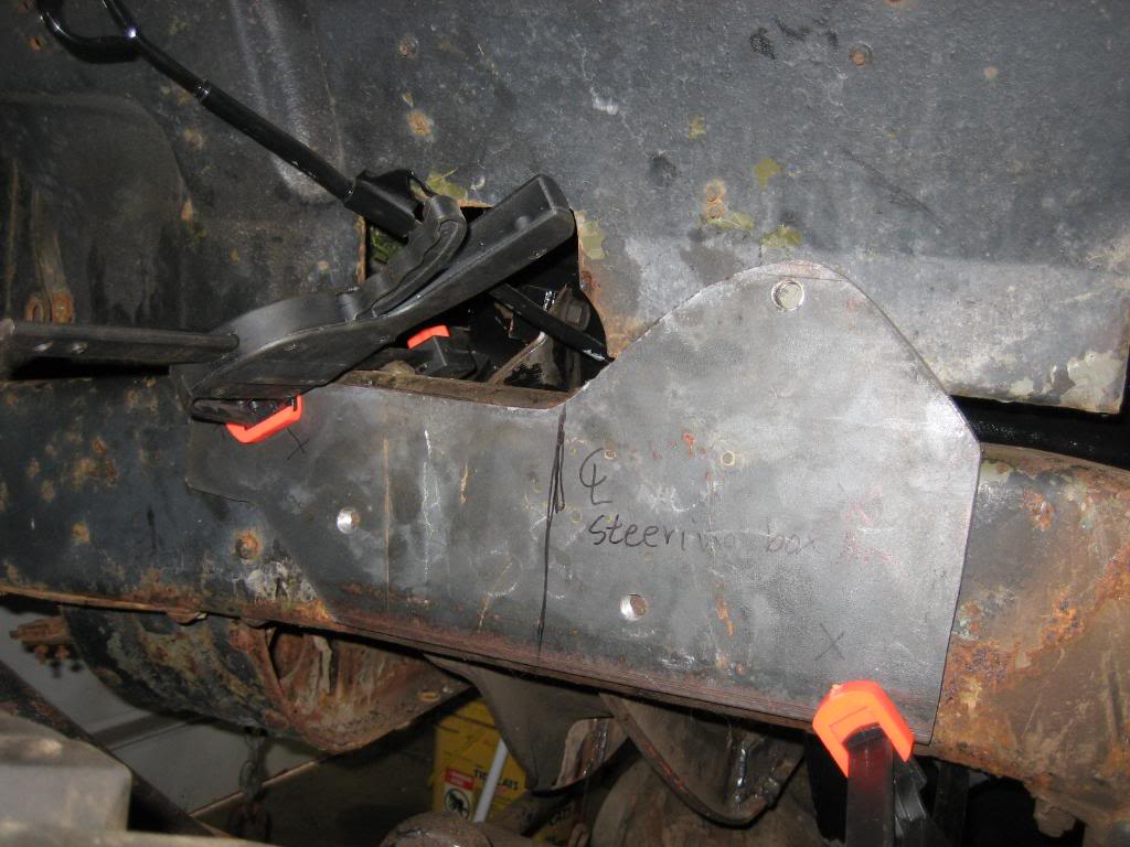
bolted the bracket back on:
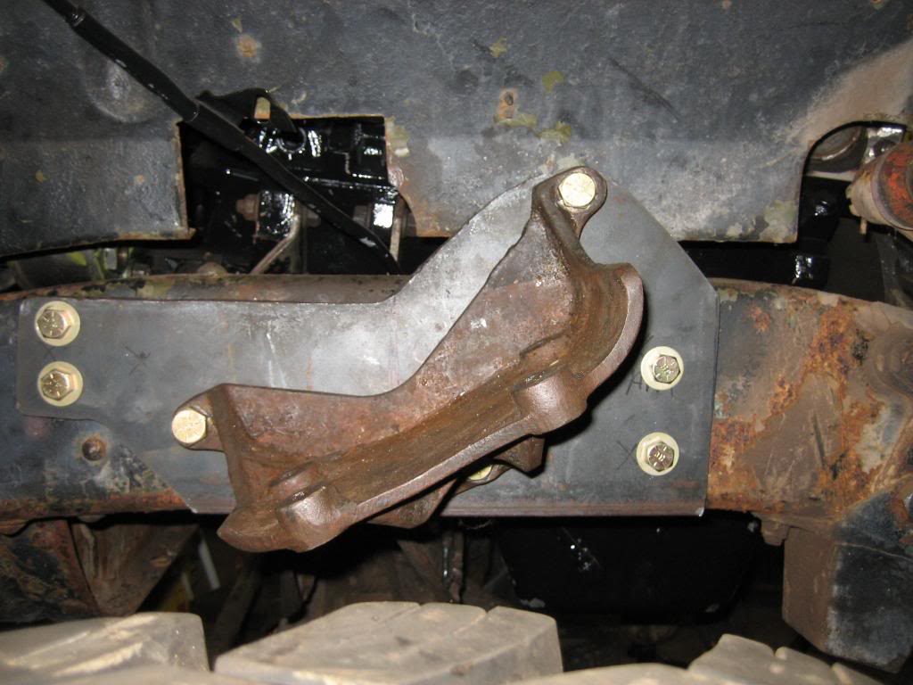
Now, once I pull the motor back out, I can take the bracket off, and drill 4 25/64" holes through both the frame and the plate. Then, take the plate off, enlarge the frame holes to a size or two over 7/16", and tap the 4 mating holes in the plate for the engine mount bolts, under the steering box bracket... and TADA, the steering box, and the motor mount occupy the same spot on the frame, the plate is held down by 8 7/16" bolts, and the frame web is pinched between the mount, and the plate, greatly reinforcing it! BRILLIANT!
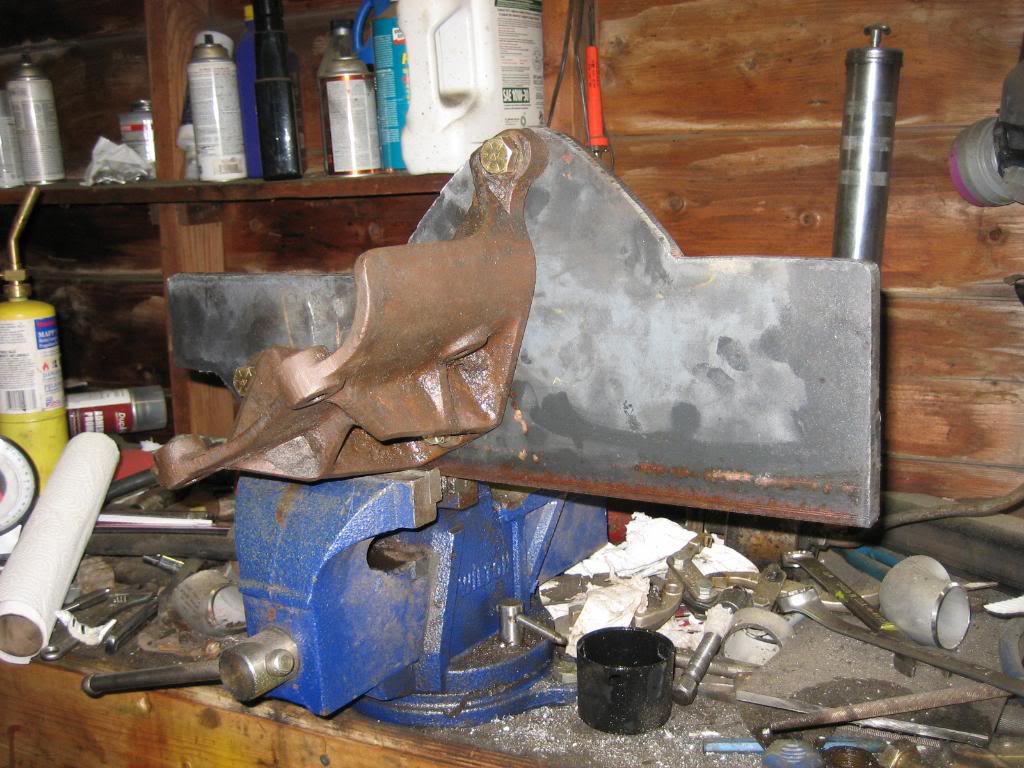
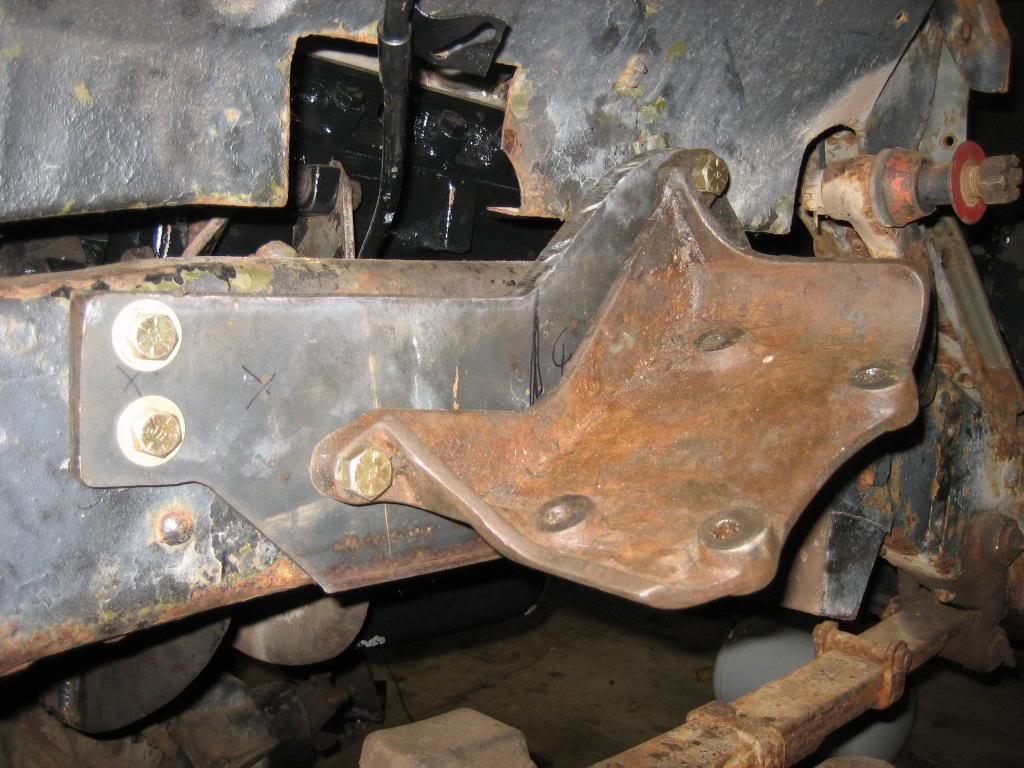
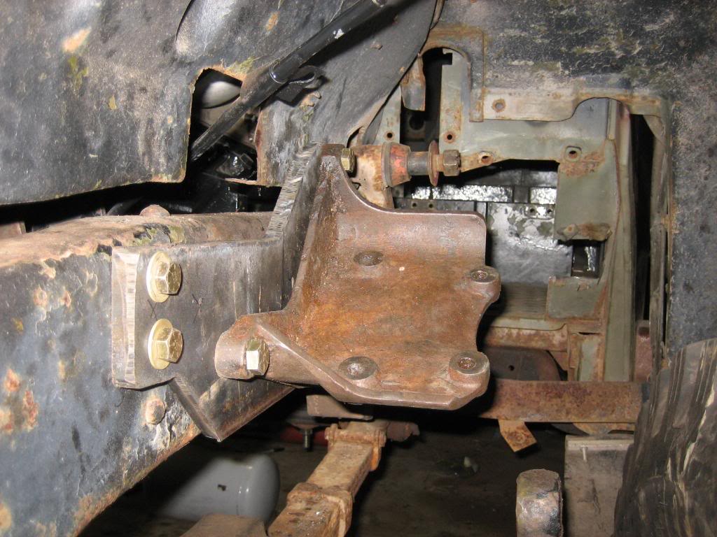
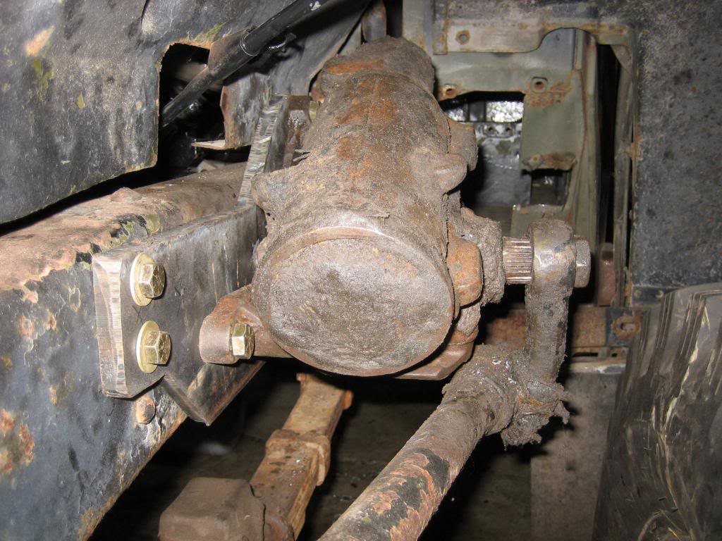
After I got the bracket on, I plopped the steering box on, slipped the original pitman arm on, and it fits beautifully:
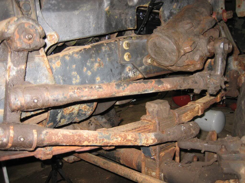
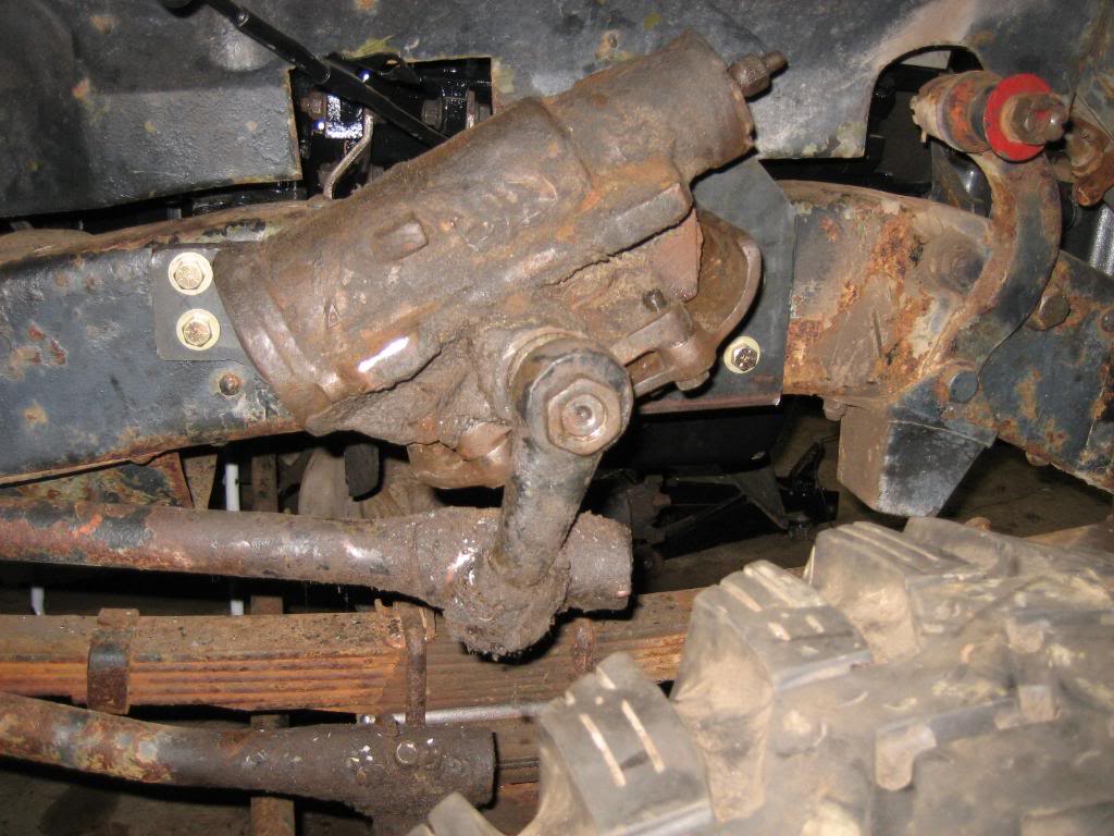
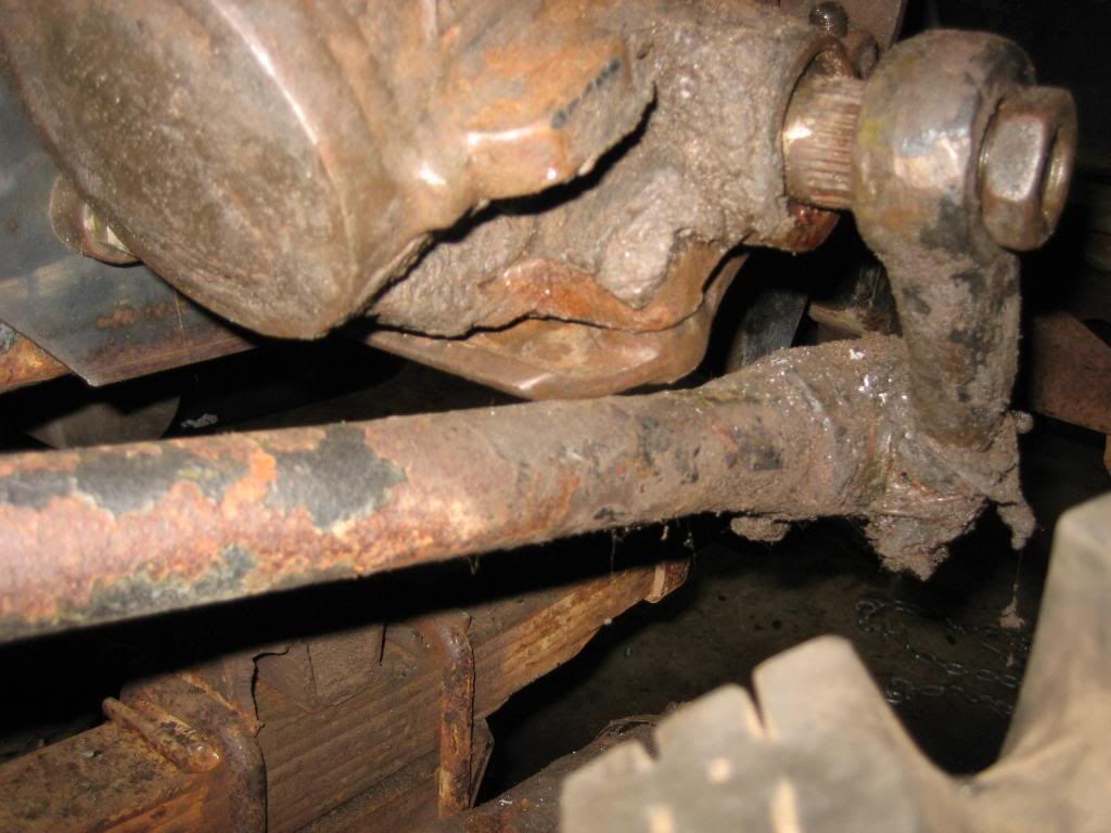
only issue is that at almost full lock to the passengers side, the top link arm hits the bracket, just barely. I'll have to clip the corner of it off with the grinder:
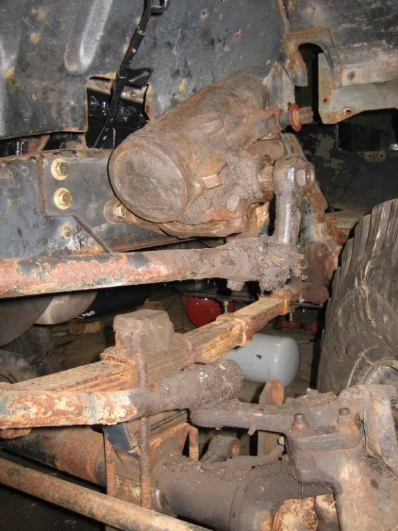
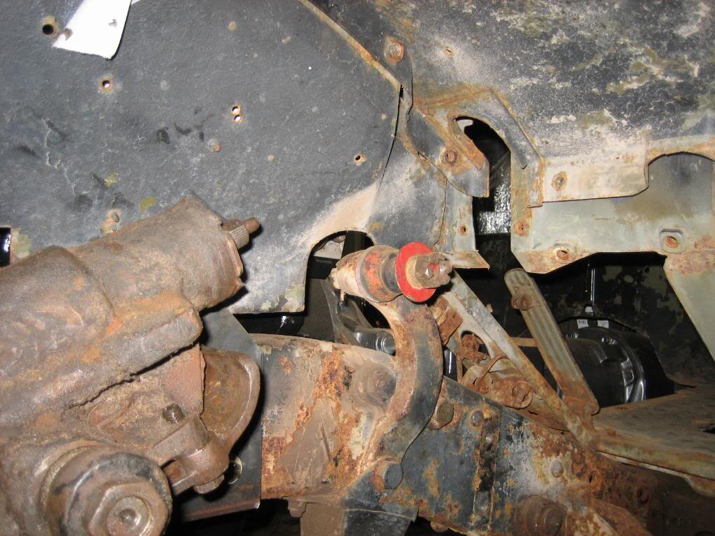
and, it's almost a straight shot up the steering shaft. I can get it to link up with a short section of flaming river shaft, and two U joints:
That's a chunk of 1/2" thick steel... the bracket is sitting at a 25* angle from the 4 mounting pads for the steering box from horizontal. I found the angle by putting the steering box on my vise, shimming it to level it, then, putting my angle finder on the pitman arm, and cycling it through it's travel. I came up with 25* angle from horizontal.
I then drilled and tapped the 1/2" plate for the 3 1/2" holes. I used fine thread so that I had 10 turns of contact. I then ground the two lower bolts off flush with the plate on the back side:
Checking the angle:
Steering box test fit:
Now, I'm sure at this point, you're thinking "jeepers, why not just through bolt it to the frame" And, here in lies the slick part of this setup... The steering box is going to sit right over where the 4 bolts for the motor mount go, so, I bolt that plate to the frame, then, drill and tap it from the inside, for the 4 motor mount bolts, so that they dont run into the steering box... I got 4 7/16" fine thread bolts for the motor mount. Below is the test fit of the plate to the frame:
and, drilled the plate for the outer set of retaining bolts. Notice the engine mount through the hole in the splash shield, so, you get an idea of how the engine is going to bolt to the plate from the inside. These through bolt:
bolted the bracket back on:
Now, once I pull the motor back out, I can take the bracket off, and drill 4 25/64" holes through both the frame and the plate. Then, take the plate off, enlarge the frame holes to a size or two over 7/16", and tap the 4 mating holes in the plate for the engine mount bolts, under the steering box bracket... and TADA, the steering box, and the motor mount occupy the same spot on the frame, the plate is held down by 8 7/16" bolts, and the frame web is pinched between the mount, and the plate, greatly reinforcing it! BRILLIANT!
After I got the bracket on, I plopped the steering box on, slipped the original pitman arm on, and it fits beautifully:
only issue is that at almost full lock to the passengers side, the top link arm hits the bracket, just barely. I'll have to clip the corner of it off with the grinder:
and, it's almost a straight shot up the steering shaft. I can get it to link up with a short section of flaming river shaft, and two U joints:
05-27-2009, 06:54 PM
#106
1.0 BAR
Thread Starter
Join Date: Feb 2003
Location: Wisconsin
Posts: 461
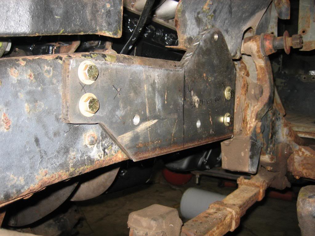
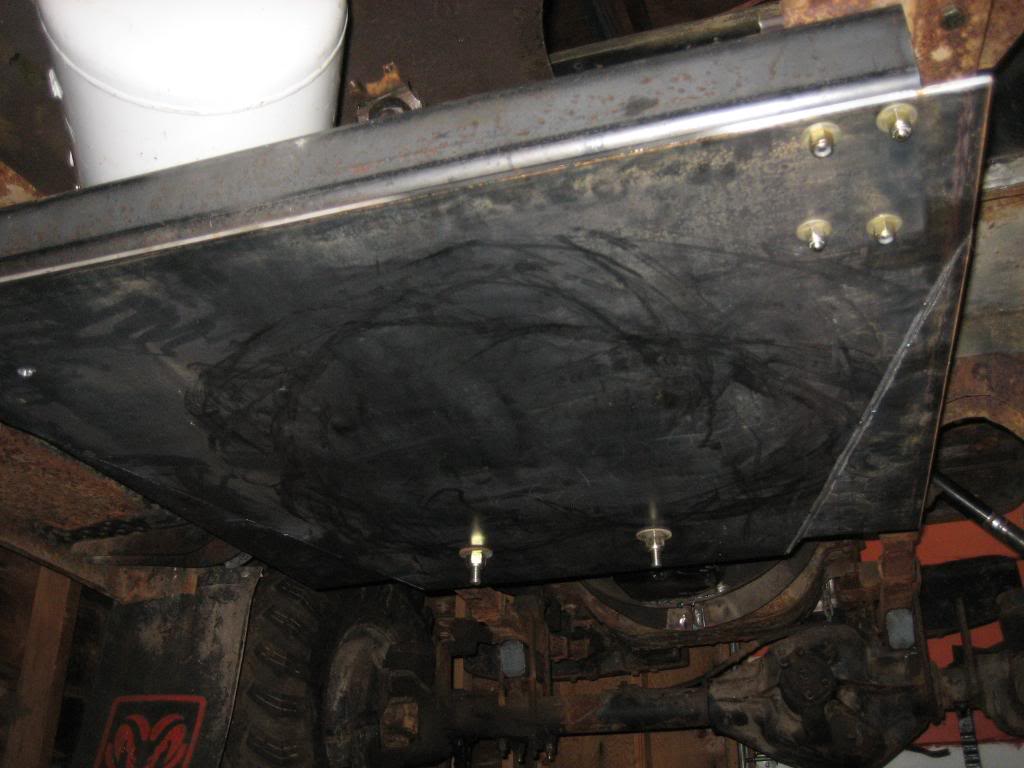
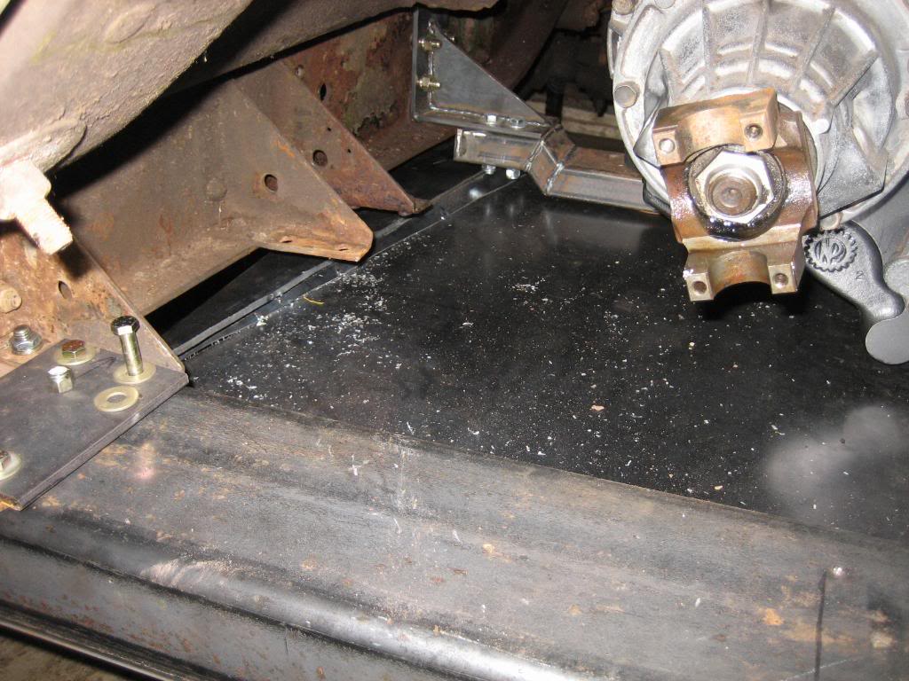
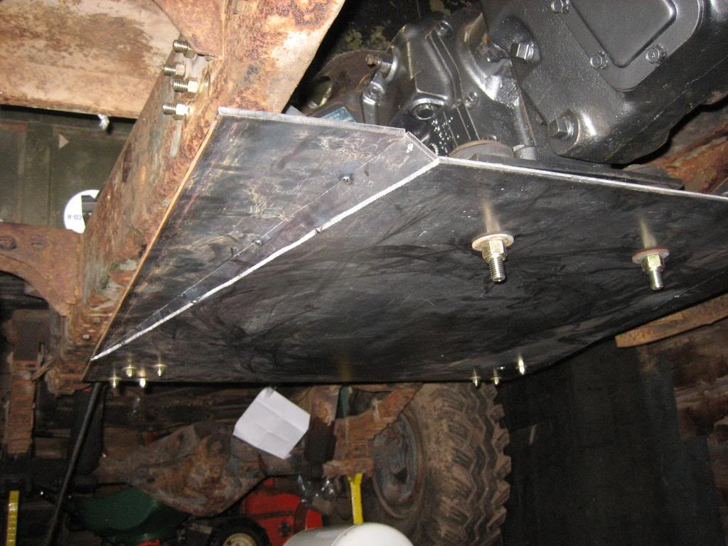
Skid plate is all mounted/mocked up... thats one BIG, HEAVY plate of steel:

This:
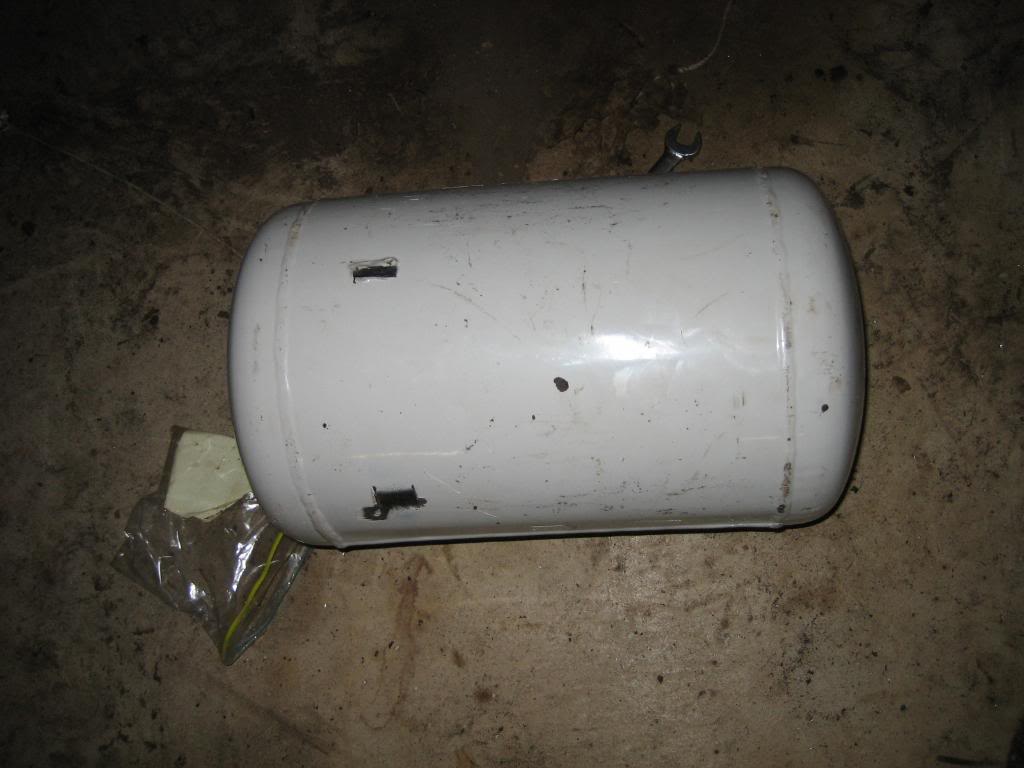
is going to go, here:
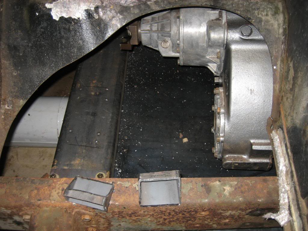
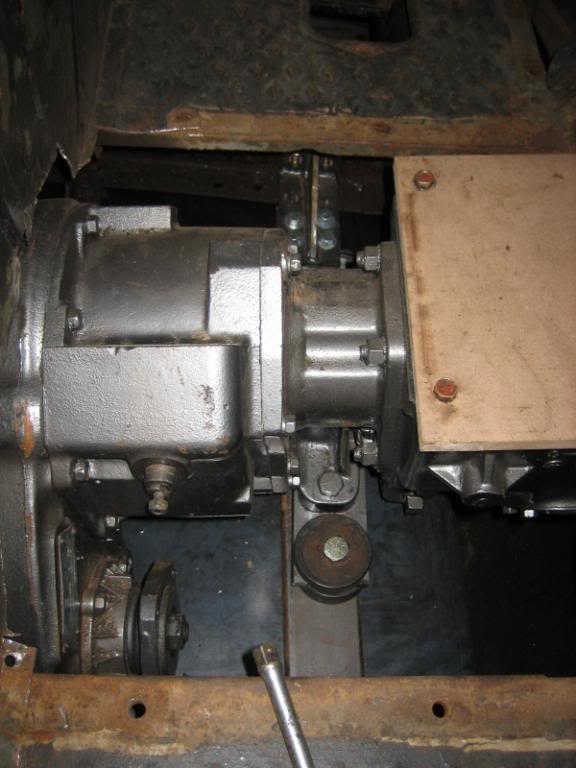
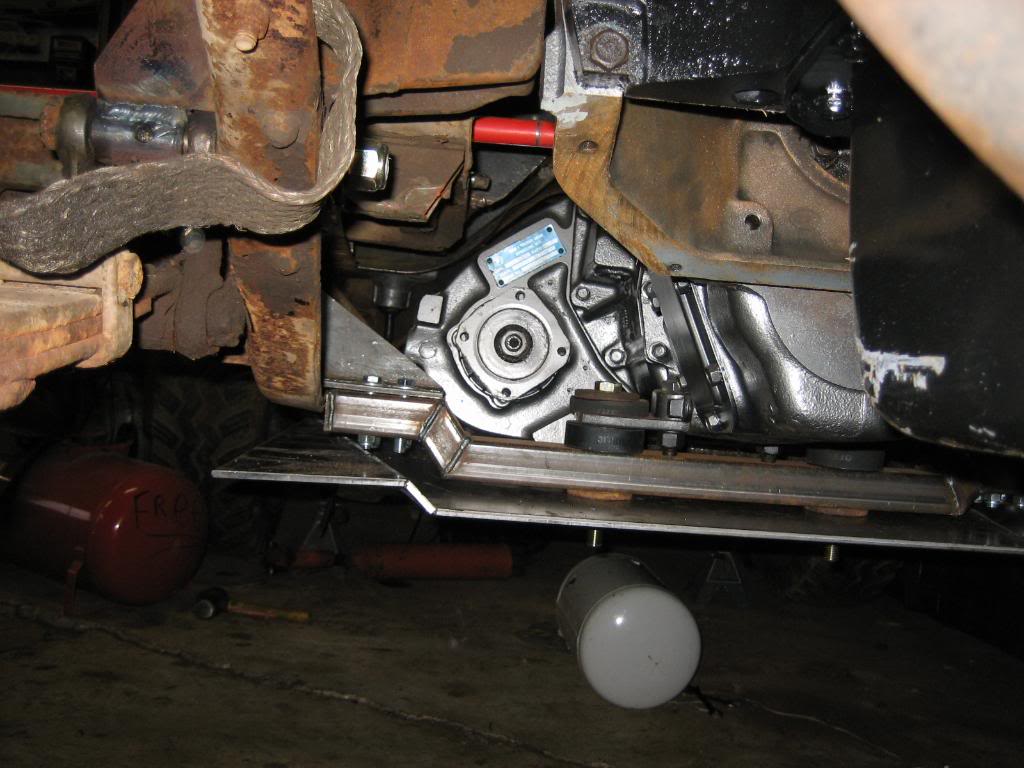
and, on the other side, Im going to mount a 2.8 gallon hydraulic tank for the winch/power steering system:
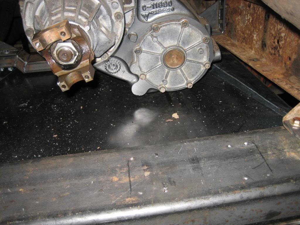
and, the driveshaft still fits:
This:
is going to go, here:
and, on the other side, Im going to mount a 2.8 gallon hydraulic tank for the winch/power steering system:
and, the driveshaft still fits:
 05-29-2009, 01:40 AM
#108
1.0 BAR
Thread Starter
Join Date: Feb 2003
Location: Wisconsin
Posts: 461
so, was looking some more at the spare saginaw PS pump I had, and decided to try and make a dedicated hydraulic pump for the winch. I'll do a How To on how to set up a resevoir type saginaw pump for remote resevoir:
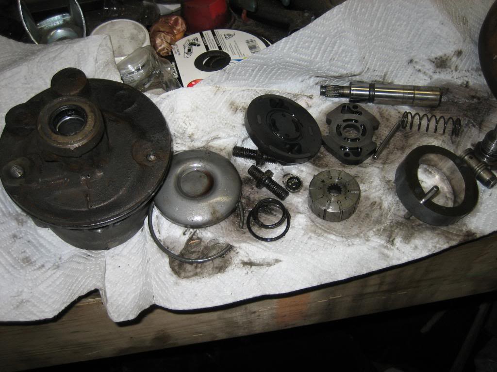
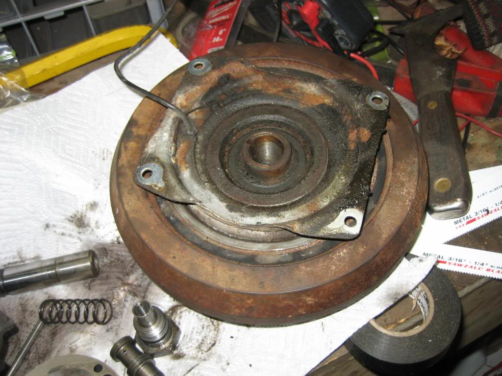
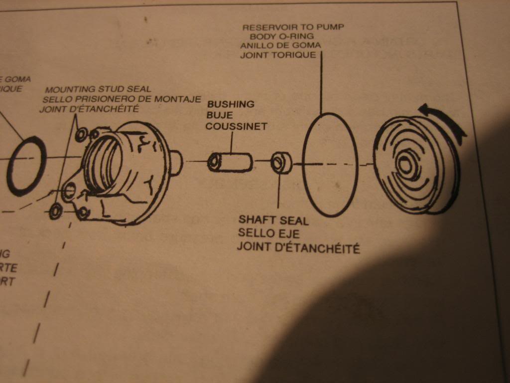
First off, diassemble the entire box. Next, toss the resevoir. You'll have the following left:
I also am planning on making this a clutched pump, so, I have a York model 210 air conditioning compressor that I took the electric clutch off of:
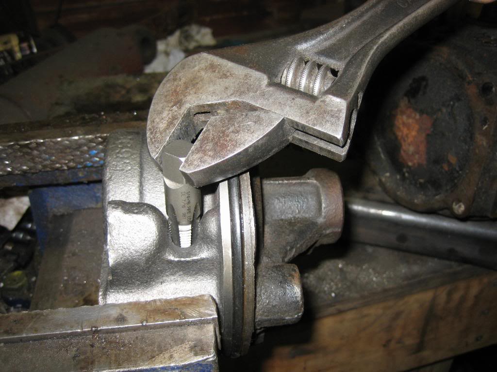
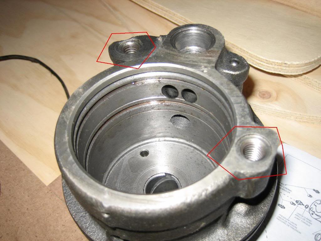
Next up, we need to make some modifications to the pump housing. there is a through hole where the pump pulls in it's fluid from the resevoir. We need to plug these. Use a 1/4" NPT drill and tap, to drill and tap the two ports for 1/4" pipe plugs:
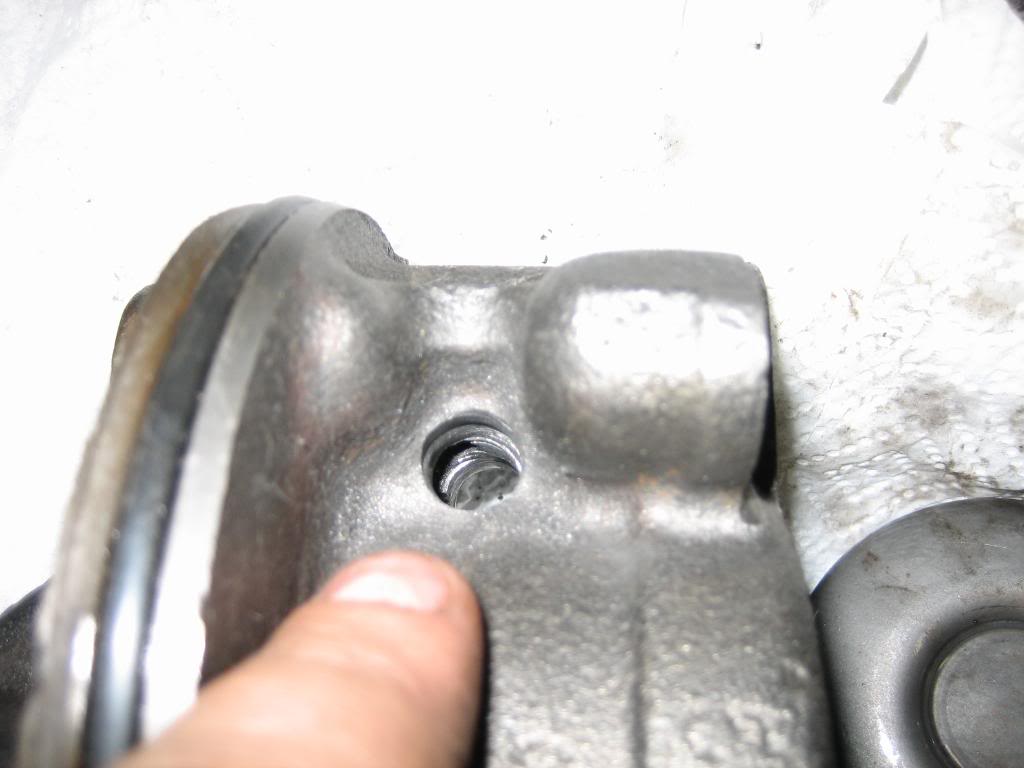
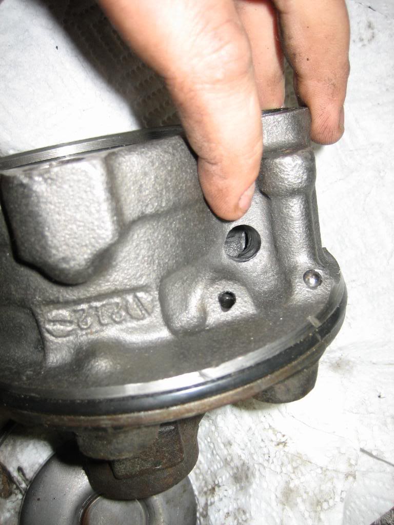
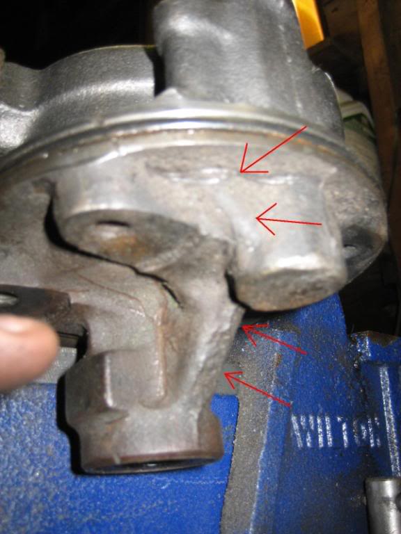
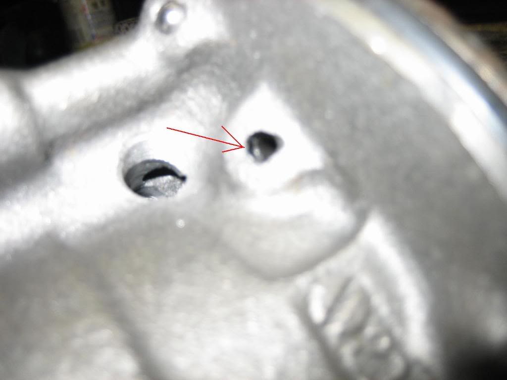
The other issue we have to overcome is the shaft lubrication hole return. The shaft has a spiral bushing which is lubricated by pressurized fluid from the high pressure side of the pump. this is then returned through the drilled passage shown:
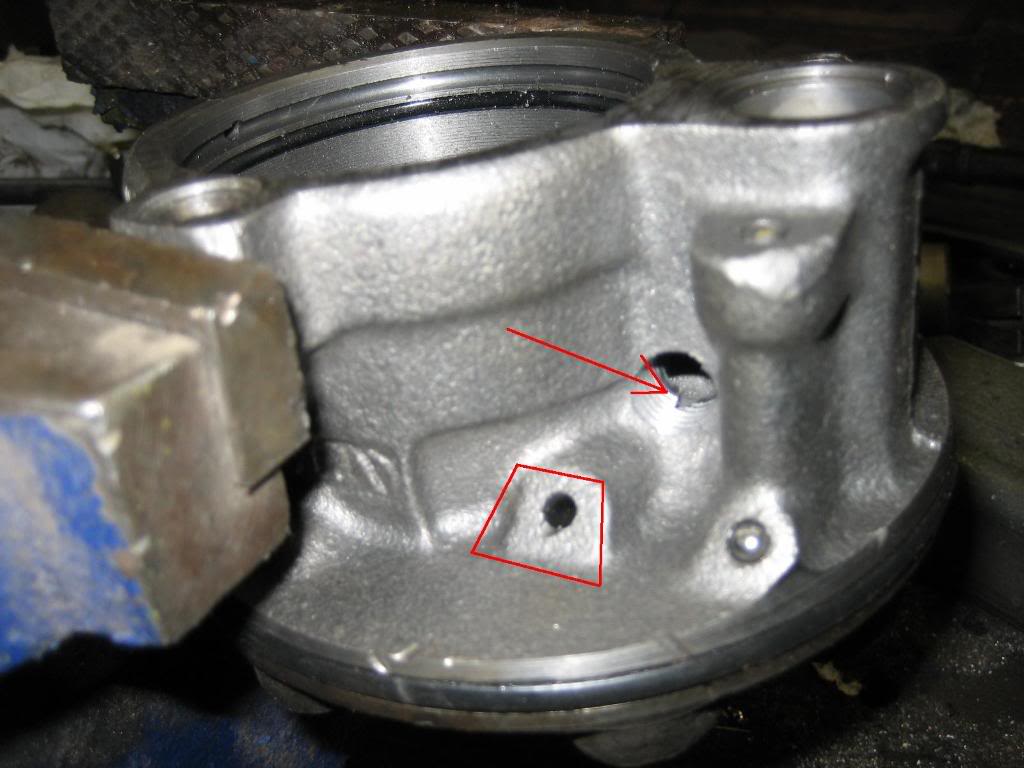
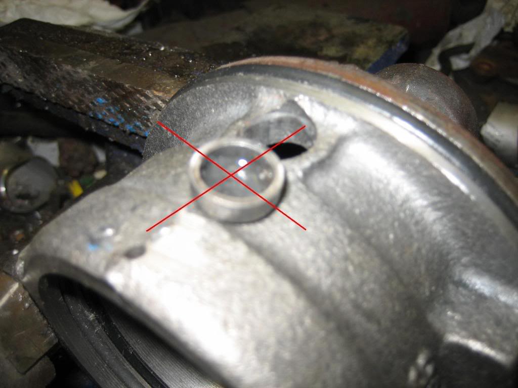
This fluid is normally emptied into the resivoir in the circled hole below. Instead, we're going to connect it into the suction side of the pump (arrow)
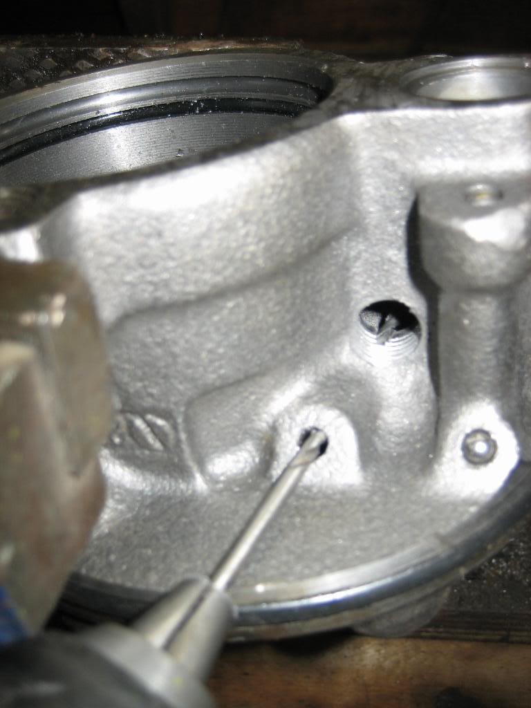
we do that by drilling through the side of the original passage. be careful not to brek out of the casting, then you'll really be screwed! Once you get the hold drilled, cut a piece of suitable steel, and weld it over the original hole to block teh fluid form dquirting out of the pump, and to force it to return to the suction side of the pump:
on the other side of the pump is a hole plugged with a cup plug. Pound the plug out, and discard it:
once it's out, drill and tap the hole for a 3/8" NPT street L fitting.
Lay out all the parts.
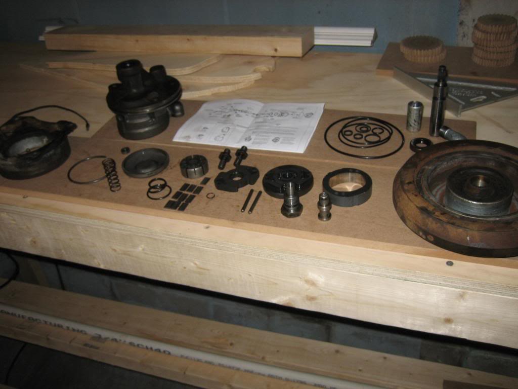
Its a good idea at this time to clean them all, as tehy have gotten dirty, and, get a rebuild kit for the pump. Ask for a 1978 dodge truck, 400 big block, W200 4X4. Mine was $13
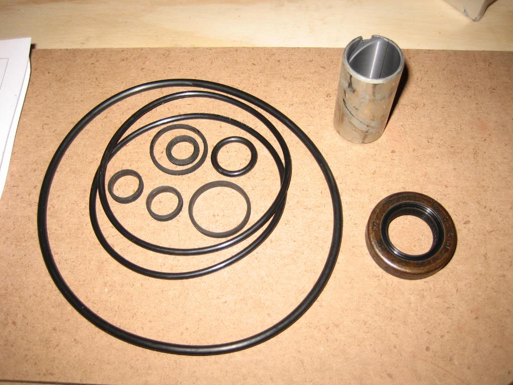
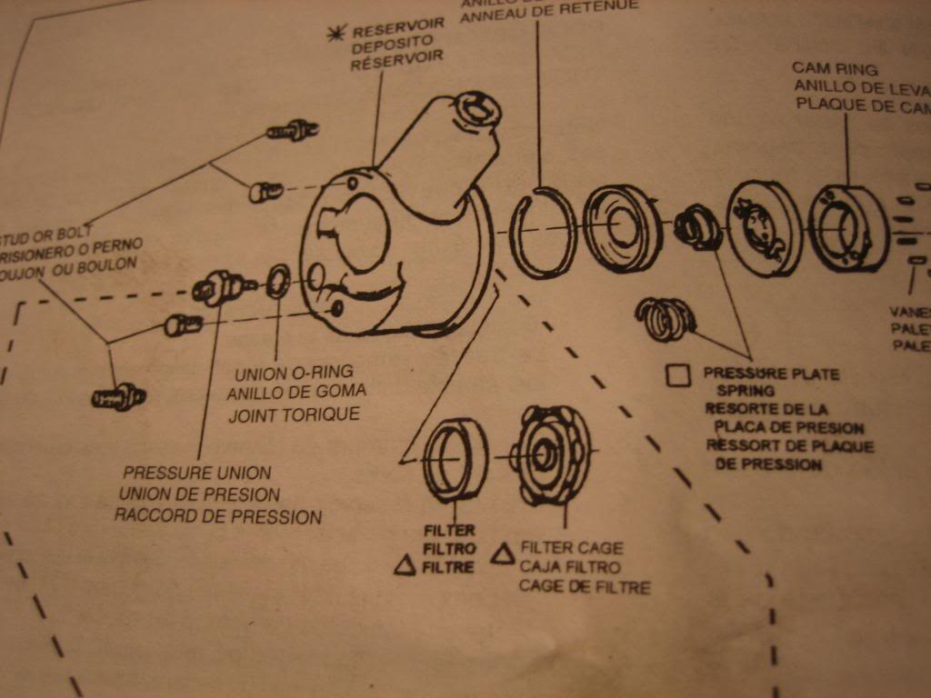
discard the following items, they wont be used. They are the resevoir O ring, and, the two mounting stud O rings. There is also two different thicknesses of O ring for the high pressure port to casting groove. discard the thicker ring, it wont be used. Also shown is the cup plug from the pump body. Install the rest of the components from te rebuild kit as shown in the kit instructions. If the kit didnt have instructions, there are pictures of the instructions from mine further below:

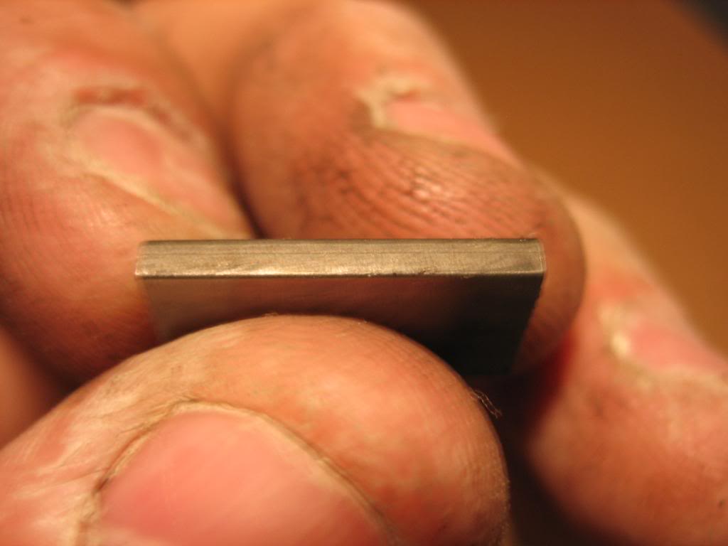
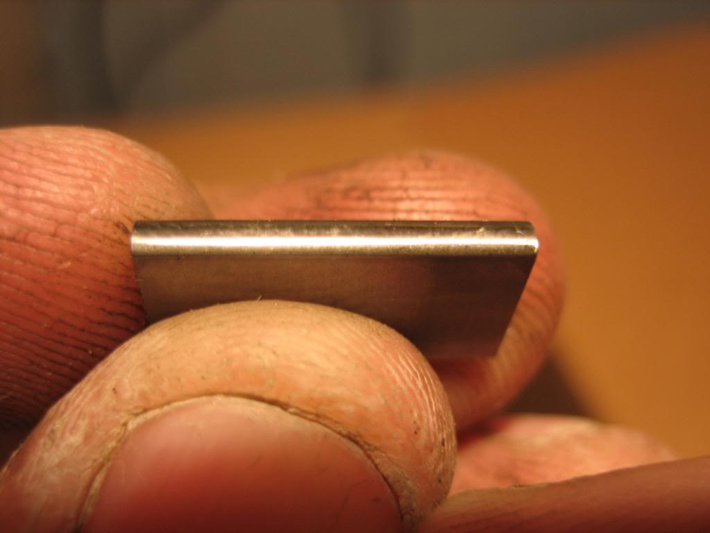
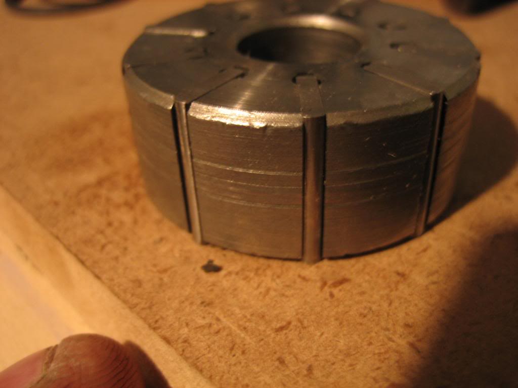
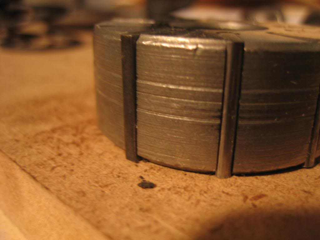
When reassembling the pump, make sure to put the vanes in the correct way. there is a smooth side, and a rough side, put the rough side in, shiny side out:
rough:
smooth:
Right:
wrong:
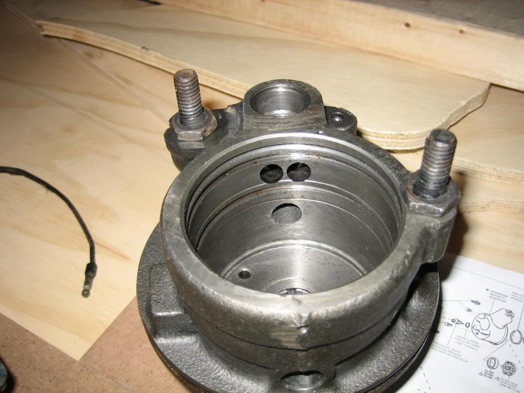
This is where those two square O rings used to go. Ignore the dent in the left top mounting ear, I dropped my housing... oops.:
just reinstall teh studs without them.
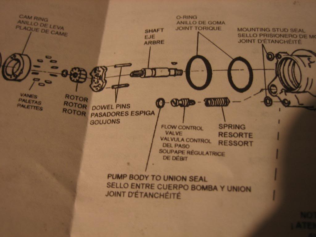
the next three pictures are of the reinstall diagram. only area it is not clear on is the direction of the vane rotor. The vane rotor has a recess on one side. The recess should face the end of the shaft that the pulley fits onto:
the rebuild is now done, for those of you who plan on constant drive. For those of you that want it clutched, you need a clutch assembly off of a york model 210 compressor:
The taper on the shaft is .25" diameter reduction per 1" of shaft length. My saginaw pump has a .75" diameter shaft, and, sticks out from the front of the seal by 1". that means we need to taper it down to .5" at the end. HOWEVER: in the above picture of the clutch, you can see the tapered hub sticks up some. The diameter at the top of that taper is .875, so, if you taper the saginal pump the full inch of length, you'll end up with the clutch hub running into the pump body before it tightens up. The solution is to only taper .45" of the shaft. there is a .05" chamfer on the end, hence why .45, instead of .5". this means that the shaft will reach the full .75" diameter .45" from the end. The end diameter should then be .638". I'd recommend welding up the hole in the center of the shaft and then milling a keyway for key stock, and redrilling for a centering bolt, but, I'll roll the dice on this one, and try relying on just the taper fit for enough friction to drive the pump. I'll be getting the shaft milled tomorrow, and will finish the rebuild this weekend...
I also plan on performing the Mods metioned in the link below, as the clutched pulley is much larger in diameter than the original pulley.
powersteering
First off, diassemble the entire box. Next, toss the resevoir. You'll have the following left:
I also am planning on making this a clutched pump, so, I have a York model 210 air conditioning compressor that I took the electric clutch off of:
Next up, we need to make some modifications to the pump housing. there is a through hole where the pump pulls in it's fluid from the resevoir. We need to plug these. Use a 1/4" NPT drill and tap, to drill and tap the two ports for 1/4" pipe plugs:
The other issue we have to overcome is the shaft lubrication hole return. The shaft has a spiral bushing which is lubricated by pressurized fluid from the high pressure side of the pump. this is then returned through the drilled passage shown:
This fluid is normally emptied into the resivoir in the circled hole below. Instead, we're going to connect it into the suction side of the pump (arrow)
we do that by drilling through the side of the original passage. be careful not to brek out of the casting, then you'll really be screwed! Once you get the hold drilled, cut a piece of suitable steel, and weld it over the original hole to block teh fluid form dquirting out of the pump, and to force it to return to the suction side of the pump:
on the other side of the pump is a hole plugged with a cup plug. Pound the plug out, and discard it:
once it's out, drill and tap the hole for a 3/8" NPT street L fitting.
Lay out all the parts.
Its a good idea at this time to clean them all, as tehy have gotten dirty, and, get a rebuild kit for the pump. Ask for a 1978 dodge truck, 400 big block, W200 4X4. Mine was $13
discard the following items, they wont be used. They are the resevoir O ring, and, the two mounting stud O rings. There is also two different thicknesses of O ring for the high pressure port to casting groove. discard the thicker ring, it wont be used. Also shown is the cup plug from the pump body. Install the rest of the components from te rebuild kit as shown in the kit instructions. If the kit didnt have instructions, there are pictures of the instructions from mine further below:
When reassembling the pump, make sure to put the vanes in the correct way. there is a smooth side, and a rough side, put the rough side in, shiny side out:
rough:
smooth:
Right:
wrong:
This is where those two square O rings used to go. Ignore the dent in the left top mounting ear, I dropped my housing... oops.:
just reinstall teh studs without them.
the next three pictures are of the reinstall diagram. only area it is not clear on is the direction of the vane rotor. The vane rotor has a recess on one side. The recess should face the end of the shaft that the pulley fits onto:
the rebuild is now done, for those of you who plan on constant drive. For those of you that want it clutched, you need a clutch assembly off of a york model 210 compressor:
The taper on the shaft is .25" diameter reduction per 1" of shaft length. My saginaw pump has a .75" diameter shaft, and, sticks out from the front of the seal by 1". that means we need to taper it down to .5" at the end. HOWEVER: in the above picture of the clutch, you can see the tapered hub sticks up some. The diameter at the top of that taper is .875, so, if you taper the saginal pump the full inch of length, you'll end up with the clutch hub running into the pump body before it tightens up. The solution is to only taper .45" of the shaft. there is a .05" chamfer on the end, hence why .45, instead of .5". this means that the shaft will reach the full .75" diameter .45" from the end. The end diameter should then be .638". I'd recommend welding up the hole in the center of the shaft and then milling a keyway for key stock, and redrilling for a centering bolt, but, I'll roll the dice on this one, and try relying on just the taper fit for enough friction to drive the pump. I'll be getting the shaft milled tomorrow, and will finish the rebuild this weekend...
I also plan on performing the Mods metioned in the link below, as the clutched pulley is much larger in diameter than the original pulley.
powersteering
Last edited by josh19wrc; 05-29-2009 at 01:43 AM.
06-01-2009, 07:24 PM
#110
1.0 BAR
Thread Starter
Join Date: Feb 2003
Location: Wisconsin
Posts: 461
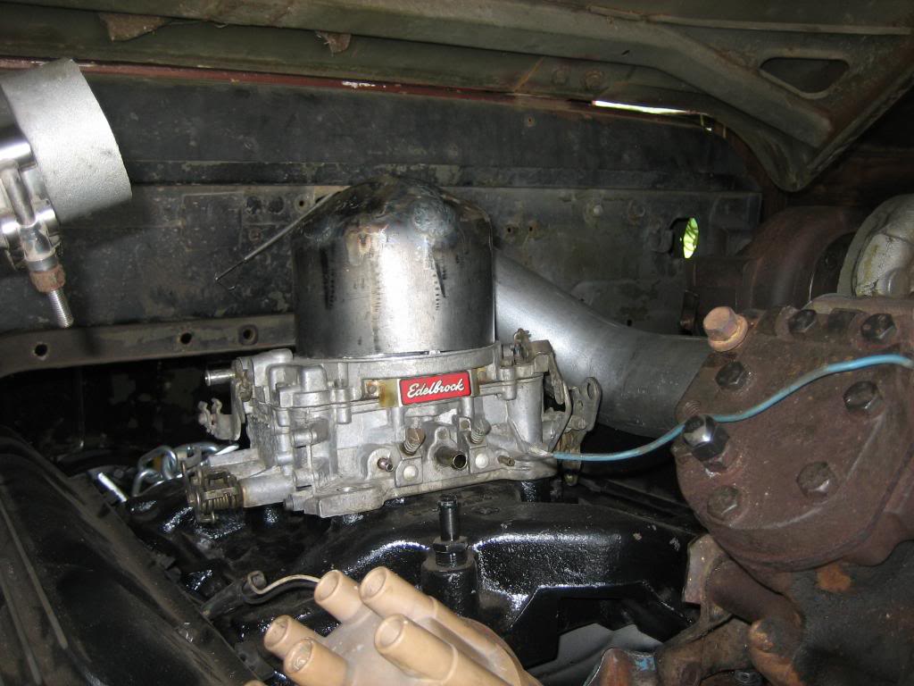
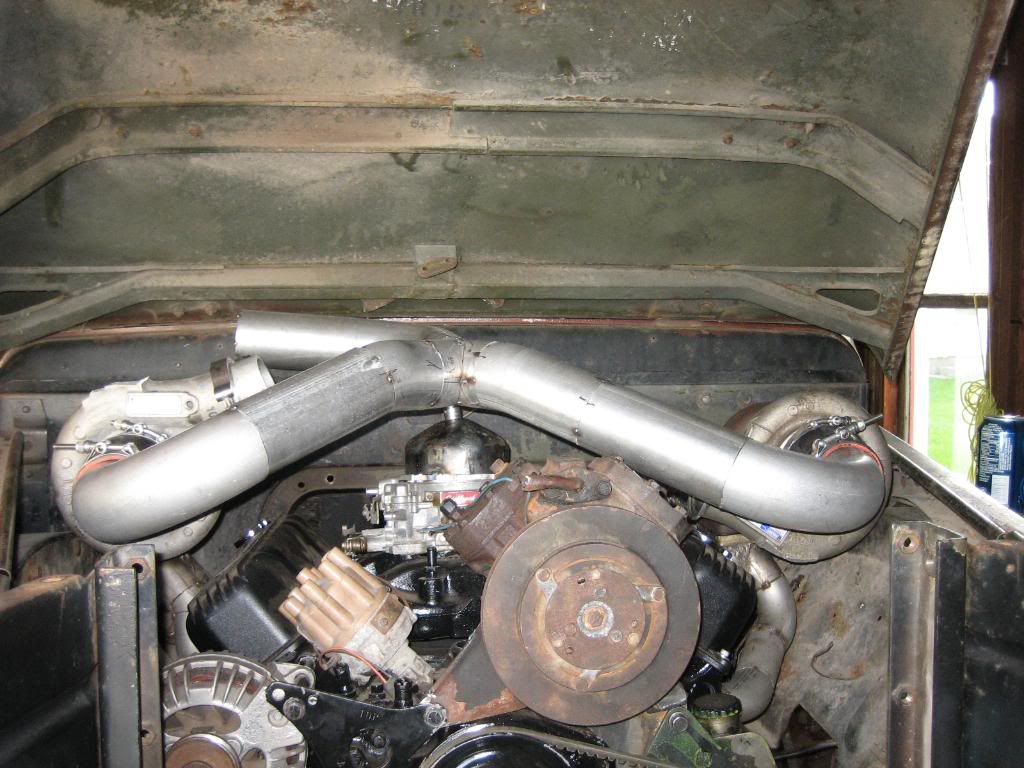
I built the carb bonnet this past weekend... took a 16"X5" sheet of 16 gauge and bent and formed and welded and ground till I got this:
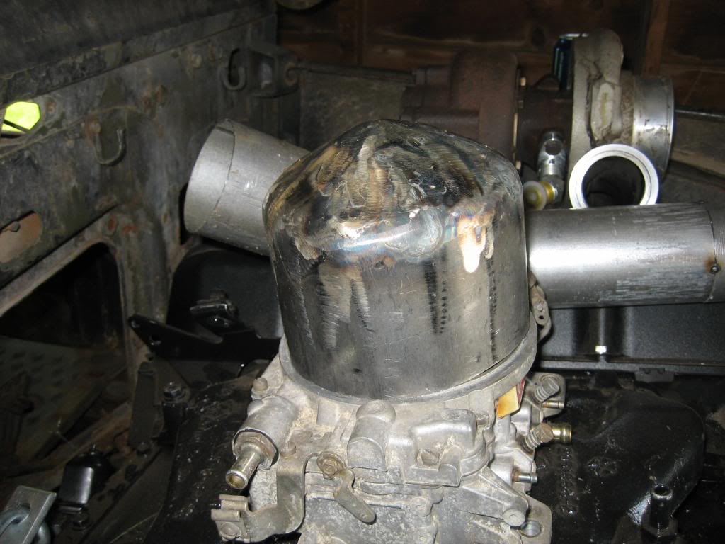
Then, cut a 1/4" thick ring to weld to the bottom for a flange.
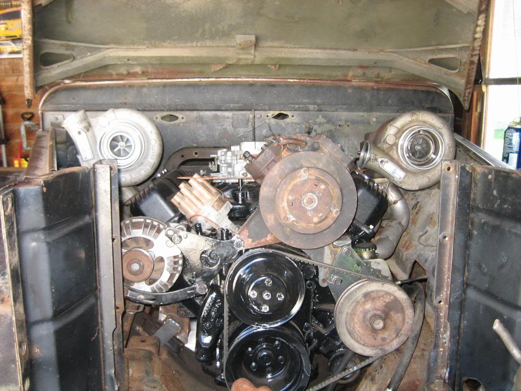
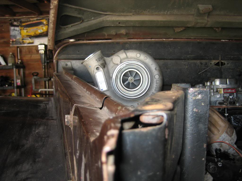
Then, tonight, I made the intake tubing:
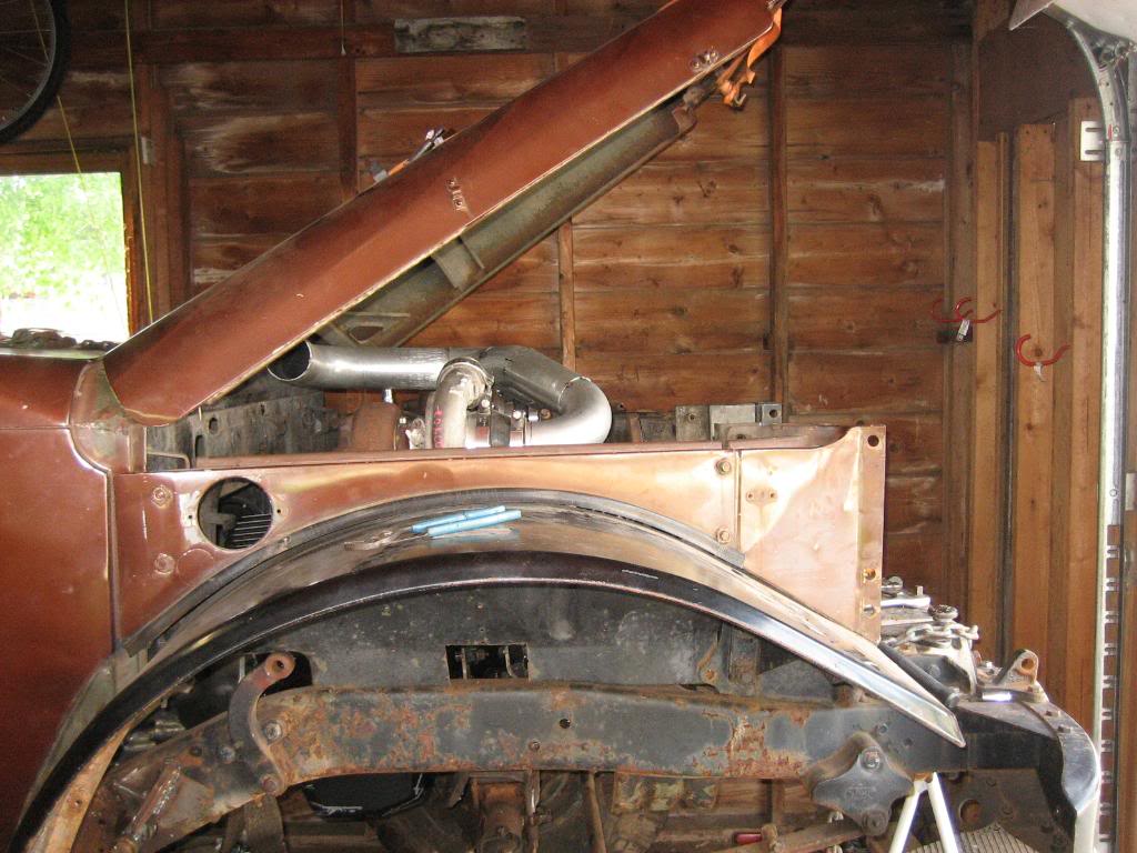
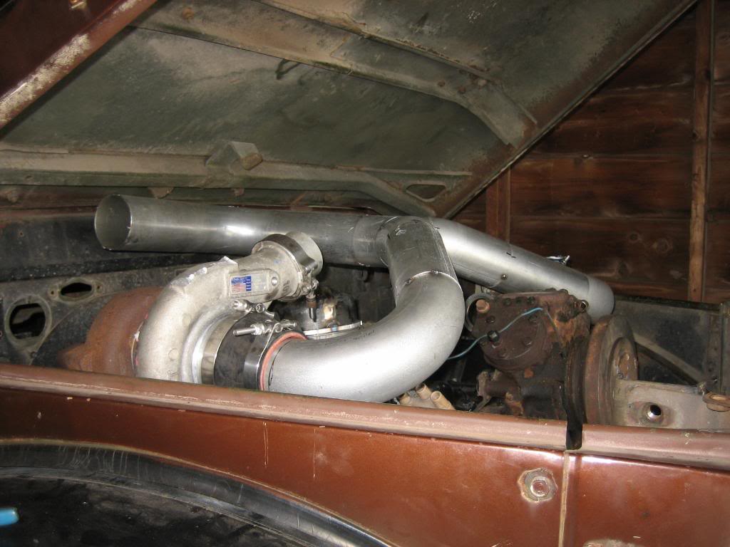
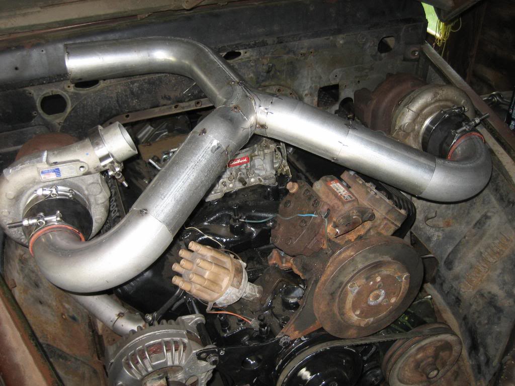
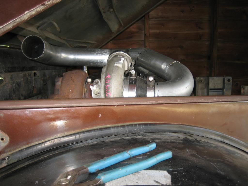
Tubing is 3", and the Jog to the passengers side at the back will be cut off right after the bend, and a 3 to 4" expander welded on. Then I'm going to build an airbox for a 4" diameter cone filter, and an airbox to encase it. Then, bring a 4" snorkel tube out of the hole in the passengers fender where the stock fjording kit came out, and run it up along side the windshield frame.
Then, cut a 1/4" thick ring to weld to the bottom for a flange.
Then, tonight, I made the intake tubing:
Tubing is 3", and the Jog to the passengers side at the back will be cut off right after the bend, and a 3 to 4" expander welded on. Then I'm going to build an airbox for a 4" diameter cone filter, and an airbox to encase it. Then, bring a 4" snorkel tube out of the hole in the passengers fender where the stock fjording kit came out, and run it up along side the windshield frame.


