
16 gauge manifold pics


Thread Starter
0.5 BAR
Joined: Jul 2008
Posts: 132
Eh I'm no expert.
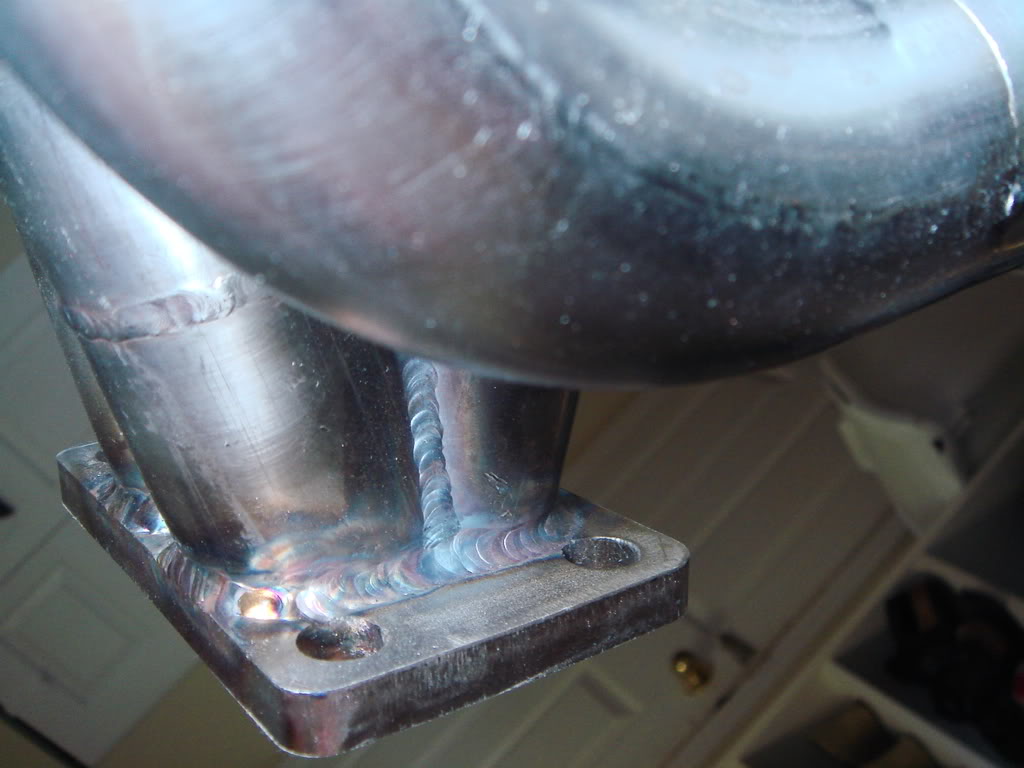
Amps are around 45, Miller Dynasty 200dx on straight DC (I've messed with the pulser a bit, a fast 200-400hz pulse seems to tighten the puddle up some, but for the most part I don't bother) , 3/32" ceriated tungsten as sharp as humanly possible, #8 gas lens, 1/4" stickout, 18cfh argon flow.
The weld size is mostly due to the puddle size required to manage the 1/16th filler. I need to travel a little on the slow side and wait for the puddle to widen out and almost drop right through, and then jab some filler in. This makes a wide bead with good penetration, but having to be so murderously on the edge of melting a big hole in order to keep the large filler from sucking all of the heat out of it is tough. Hence the inconsistency. If you don't make the puddle that big the filler just sticks, blobs, etc.
With smaller filler I could run maybe 5 amps hotter and travel faster, have the same penetration and a narrower, more consistent bead. That's more what I am after as the HAZ should be smaller.
You could still go slower with less amps and have the wide bead, but you will need to be really skilled at advancing the filler with you "feeder hand", as you'll be add like an inch worth of 0.035" every dip. Better to run hotter and faster IMO.
So yeah, slightly slower and more amperage will do it, you just need to wait for the puddle to grow and then be careful to not blow a hole in it.
I think schedule 10 is overkill for headers is welded/designed properly, but I d think the 16 gauge is a little light. I think after this run I am going to try something like 14 gauge @ ~0.083" as a good compromise. It's slightly thin for 1/16" filler still and almost too fat for 0.035 though. I will probably stay with 0.035" and just feed it like a mad man at around 60-65 amps or so.
Thread Starter
0.5 BAR
Joined: Jul 2008
Posts: 132
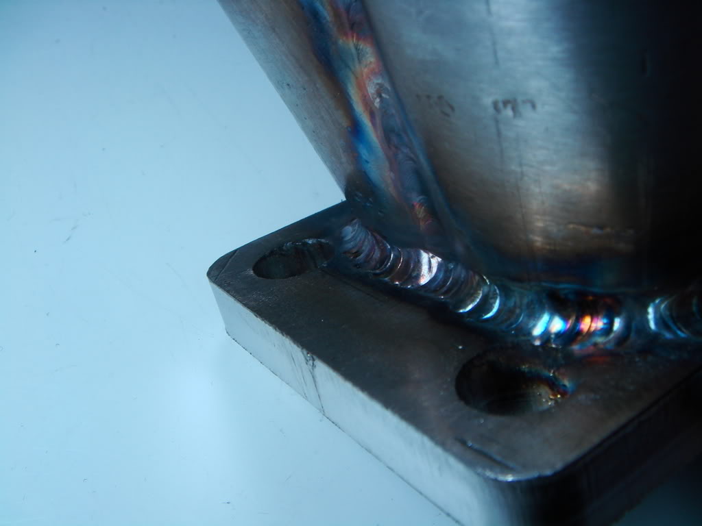
Ok so I tried 0.035" and 50 amps. Definitely made it easier to be consistent.
However, I also tried again with 1/16" using 60 amps, and it might actually be even better. You need to play with the footpedal a bit, but you don't have to try to advance that thin tig wire like a maniac all the time like with the 0.035". I'll just keep experimenting.
As far as the backpurge goes- sealing the gas fitting to the tube helped immensely.
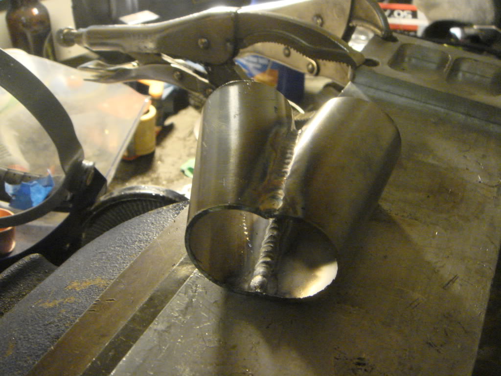
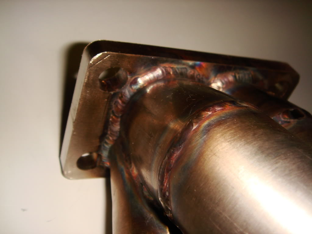
Check this out, the weld you can see on the inside of the collector is the backside of the weld on the bottom. You almost can't tell the backside/inside of the weld form the outside.
I am still refining my welding technicque on the thinwall, but it's coming along nicely.
However, I also tried again with 1/16" using 60 amps, and it might actually be even better. You need to play with the footpedal a bit, but you don't have to try to advance that thin tig wire like a maniac all the time like with the 0.035". I'll just keep experimenting.
As far as the backpurge goes- sealing the gas fitting to the tube helped immensely.
Check this out, the weld you can see on the inside of the collector is the backside of the weld on the bottom. You almost can't tell the backside/inside of the weld form the outside.
I am still refining my welding technicque on the thinwall, but it's coming along nicely.
Thread Starter
0.5 BAR
Joined: Jul 2008
Posts: 132
With a brace, yeah I think they'll hold up pretty good.
Without a brace I don't think it's fair to demand that a 16ga mani support ~30lbs of vibrating turbo/wastegate/downpipe whilst heated over 1000 degrees over and over again though, just not reasonable.
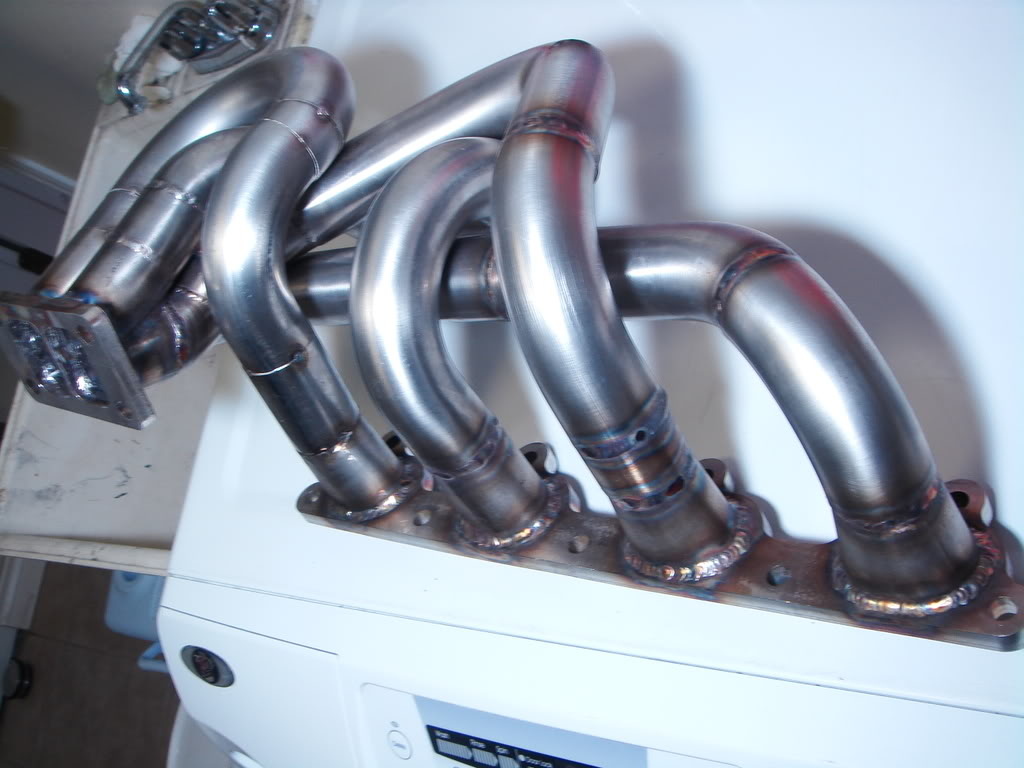
That's fine, it's job is to spool the turbo, not be a structural member- a brace is easy enough to make. U bends sure are nice to work with, I hate weld els now.
Without a brace I don't think it's fair to demand that a 16ga mani support ~30lbs of vibrating turbo/wastegate/downpipe whilst heated over 1000 degrees over and over again though, just not reasonable.
That's fine, it's job is to spool the turbo, not be a structural member- a brace is easy enough to make. U bends sure are nice to work with, I hate weld els now.

1.0 BAR
Joined: Aug 2005
Posts: 339
Are you going to brace to the flange or to the block? I remember someone once telling me that if you brace at the block the heat cycles will make it get all warped since the block doesnt change with it and that it will vibrate itself to death? Something along the lines of that anyway. A few years ago Aaron Weir made one, and he made some pretty nice gussets on the bends.


