My Divided Manifold Quick Spool Valve
 06-06-2013, 02:55 AM
#1
0.0 BAR
Thread Starter

Join Date: May 2013
Posts: 24
I switched to a TH400 last year and getting a decent high stall converter that can hold the power my car makes is not easy to do. As I don't want to use NOS to launch, I decided the best solution was to make my own QSV as I didn't want to cut up my 6Boost manifold just to fit a QSV that requires an undivided manifold.
Almost everyone will tell you that you that cannot have a divided manifold quick spool valve. Well, yes you can!
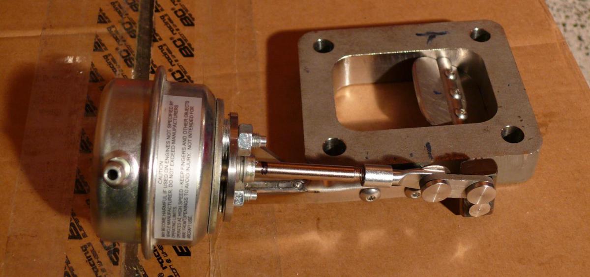
All the pics and details are in my QSV article.
Toyota Supra MKIV : Divided Manifold Quick Spool Valve
Here's one of the pics just to get your attention.
Almost everyone will tell you that you that cannot have a divided manifold quick spool valve. Well, yes you can!
All the pics and details are in my QSV article.
Toyota Supra MKIV : Divided Manifold Quick Spool Valve
Here's one of the pics just to get your attention.
 06-07-2013, 09:36 PM
#2
0.0 BAR
Thread Starter
Join Date: May 2013
Posts: 24
I connected up the wastegate hose and went for a test run today. It feels even faster off the line with the 2600rpm converter then it used to be with the 3800rpm converter.
Only problem is that once I got it really hot it started sticking and it will only move between 1/4 open and 3/4 open until it cools down. I'll pull it all apart and trim it a bit more. A little leakage when closed is a lot better then having it jamb when hot.
Once its not jamming, I'll do some data logging.
06-08-2013, 01:10 AM
#3
0.0 BAR
Thread Starter
Join Date: May 2013
Posts: 24
I just pulled it apart and it was the shaft that seized. I thought the engineer had made it a bit too tight.  I'll reduce the shaft size a bit to allow for carbon buildup and heat expansion and hopefully that will fix it.
I'll reduce the shaft size a bit to allow for carbon buildup and heat expansion and hopefully that will fix it.
08-28-2013, 07:58 PM
#4
0.0 BAR
Thread Starter
Join Date: May 2013
Posts: 24
I have changed the shaft material to Nitronic 60 S/S which theoretically should not bind (gall) with the flange S/S (302 or 316). It now also has a bit more clearance which will help as well.
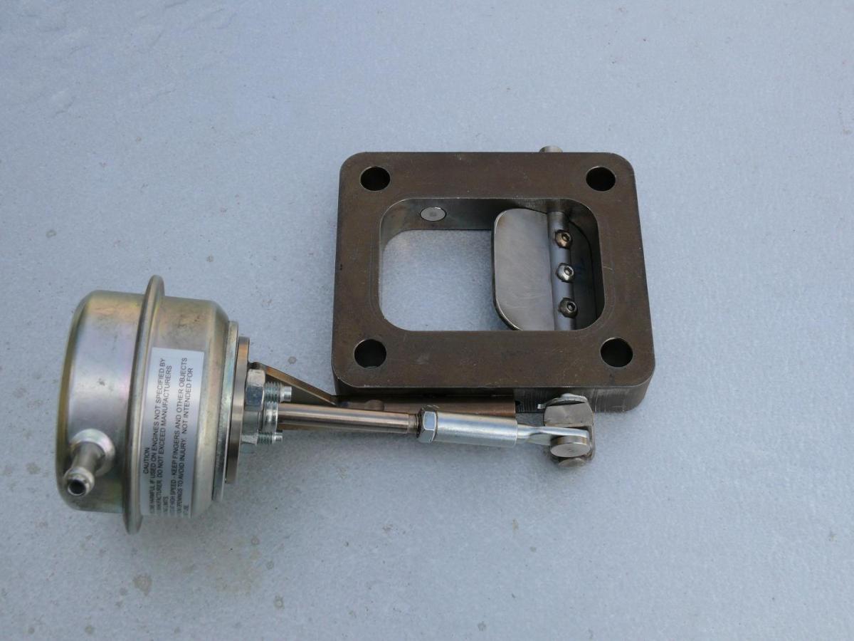
I have also had the QSV modified so that the shaft is now 1/3rd of the distance from the lower leading edge of the flap. This moves the shaft to the center of pressure on the flap so that it can open more easily. The actuator is still the same one I have used all along.
With my wife taking a video of the QSV, I have brake boosted the car in the garage to check how easily it opens. I can report that it now opens smoothly and evenly when the boost rises from 5 psi (when it cracks open) up to 10 psi when it is fully open. This is a big improvement on how it was with the shaft in the center of the flap where it was very jerky and slow to open, so problem #1 solved.
Unfortunately when testing it on the road it still sputters at around 8-9 psi. I'm starting to think this may be a tuning issue, so I'm changing the converter to a higher stall one next week (that can still hold the power) and I will then take it to my tuner to get it fully tuned with the QSV. I'll update this thread once that's done.
10-06-2013, 07:08 PM
#5
0.0 BAR
Thread Starter
Join Date: May 2013
Posts: 24
I finally got it tuned and the QSV is working perfectly. Just before the tune I threw a new set of plugs in it and it didn't misfire at all on the dyno when he first tried it, so all this time it was plugs causing my misfire. Strange how it was okay with the QSV open, but I guess the cylinder pressures were lower.
So I can finally report that my divided manifold QSV is working perfectly! Yah!
So I can finally report that my divided manifold QSV is working perfectly! Yah!
 10-17-2013, 12:32 AM
#7
0.0 BAR
Thread Starter
Join Date: May 2013
Posts: 24
I must say its fun talking to yourself.
Here is the dyno sheet. The QSV is the red line. See how much quicker it builds boost. Max power is lower due to switching converter from 2600rpm stall to 3000rpm stall converter that slips more.

Here is the dyno sheet. The QSV is the red line. See how much quicker it builds boost. Max power is lower due to switching converter from 2600rpm stall to 3000rpm stall converter that slips more.
 10-18-2013, 06:42 PM
#10
0.0 BAR
Thread Starter
Join Date: May 2013
Posts: 24
What can be the most expensive part of installing a QSV is that it increases the height of your turbo by 3/4", which requires down pipe changes, oil drain pipe, oil feed line, compressor pipe changes and possibly intake changes as well.
A possibly better option for a one-off setup is to install it in the base of the turbine housing?
A possibly better option for a one-off setup is to install it in the base of the turbine housing?


