Holset VGT HE351VE Controller
 05-18-2010, 02:29 PM
#61
0.0 BAR
Thread Starter

Join Date: Mar 2009
Posts: 45
Yeah, approximating wastegate actuator area on left to get approximate shaft force. Guessing how long the VGT arm on the holset is on the right. It's outside, tucked away, in a box and can't be bothered dragging it out to measure it so I just approximated it as 2cm and 3cm.
Servo heat tolerance: no idea. Their website don't say anything about temps. I found a servo that's cheaper with higher torque with the option of upgrading to robotics servos with even more torque at higher voltage. I'm going to try test out the algorithm and heat tolerance by running a servo in place of the wastegate actuator, mounted off the compressor housing in a similar to what I would like to do with the holset. That way I can sorta get an idea of whether it's going to work (or melt away or not be quick enough) before I install the 351VE.
How big an engine are you planning on running the turbo on? I've got a 1.8 and a 38mm wastegate, you think it'll be enough?
 05-22-2010, 02:18 AM
#62
0.0 BAR

Join Date: Sep 2008
Posts: 22
Hi there CivicTsi!
I'm really itching to start building my own controller... can you help? ... what should I get besides the Picaxe?... Can you provide us/me with the parts list and some guidelines to at least start to get everything ready?
Thanks man!
I'm really itching to start building my own controller... can you help? ... what should I get besides the Picaxe?... Can you provide us/me with the parts list and some guidelines to at least start to get everything ready?
Thanks man!
05-22-2010, 09:37 AM
#63
0.0 BAR

Join Date: May 2010
Posts: 20
Hey, I had a good look at your code. The second line after close:, and open: headers (readadc 2,b1 'Take MAP sensor reading and save to memory block b1) can be deleted? Open and Close subroutines don't require a MAP reading as it just checks if current position is close enough to desired to use fineopen/close then sets servopos 2 to 150+-18 if it isn't. The same line which appears just before the main: header can also be removed as you check MAP two lines later.
Do you plan to set up trending with B5 and B6? They aren't used elsewhere in the program.
Do you intend to make target boost adjustable later on down the track?
With the ESC, how are you running 12v+ into it when it's rated to 3S only? What happens when the VGT rack is moved into max position in the beginning when recording values for max open and shut values? Does the ESC's current draw spike in trying to fight the endpoint?
Update on my end: I bought a high torque servo(hitec hs-5805mg) off ebay and should be here next week. Started making a compressor housing servo mount for T25.
 05-30-2010, 09:04 PM
#66
0.0 BAR
Thread Starter
Join Date: Mar 2009
Posts: 45
Hey, I had a good look at your code. The second line after close:, and open: headers (readadc 2,b1 'Take MAP sensor reading and save to memory block b1) can be deleted? Open and Close subroutines don't require a MAP reading as it just checks if current position is close enough to desired to use fineopen/close then sets servopos 2 to 150+-18 if it isn't. The same line which appears just before the main: header can also be removed as you check MAP two lines later.
Do you plan to set up trending with B5 and B6? They aren't used elsewhere in the program.
Do you intend to make target boost adjustable later on down the track?
With the ESC, how are you running 12v+ into it when it's rated to 3S only? What happens when the VGT rack is moved into max position in the beginning when recording values for max open and shut values? Does the ESC's current draw spike in trying to fight the endpoint?
Update on my end: I bought a high torque servo(hitec hs-5805mg) off ebay and should be here next week. Started making a compressor housing servo mount for T25.
Do you plan to set up trending with B5 and B6? They aren't used elsewhere in the program.
Do you intend to make target boost adjustable later on down the track?
With the ESC, how are you running 12v+ into it when it's rated to 3S only? What happens when the VGT rack is moved into max position in the beginning when recording values for max open and shut values? Does the ESC's current draw spike in trying to fight the endpoint?
Update on my end: I bought a high torque servo(hitec hs-5805mg) off ebay and should be here next week. Started making a compressor housing servo mount for T25.
05-30-2010, 10:51 PM
#67
0.0 BAR
Thread Starter
Join Date: Mar 2009
Posts: 45
Ok, here it is. A parts list with instructions:
ESC HobbyWing EZRUN-25A-L Brushless ESC for 1/18 Car (Version 2)
Programming Card LED Program Card For HobbyWing RC Car Brushless ESC
Picaxe starter kit SparkFun Electronics - PICAXE-18X Starter Pack
Picaxe programming cable SparkFun Electronics - PICAXE USB Programming Cable
(Serial cable is cheaper if your computer supports it)
MAP sensor (Any)
100k ohm linear taper potentiometer 100K-Ohm Linear-Taper Potentiometer - RadioShack.com
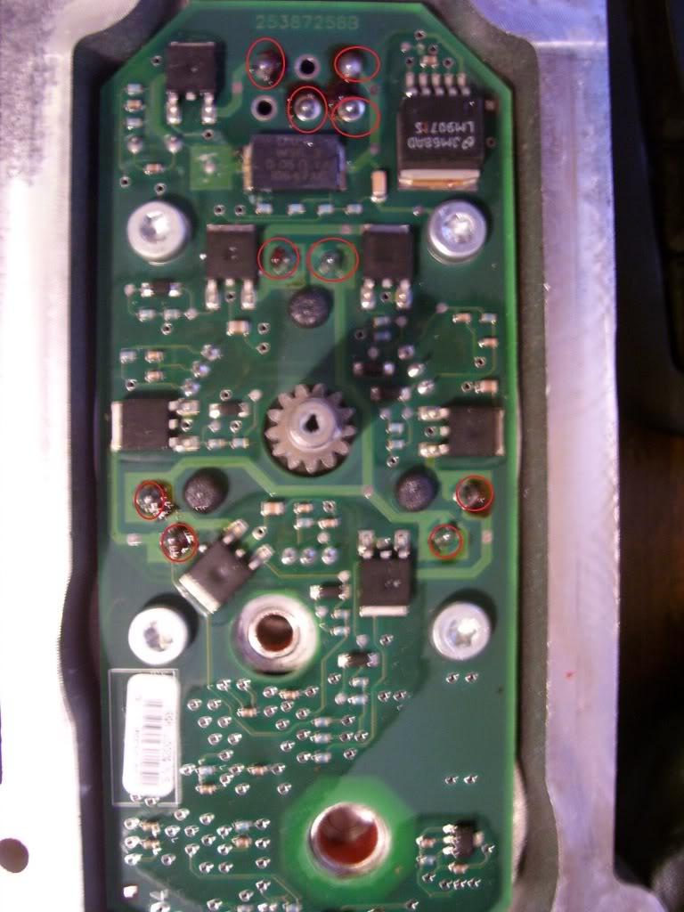
Remove board by desoldering circled areas:
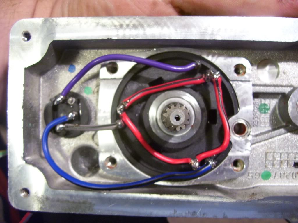
Once the board is loose, solder the connections like so:
Drill a hole and mount the pot:
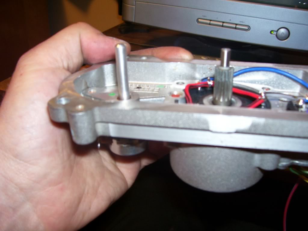
Trim the shafts on the pot and gearbox with a Dremel so that they interlock.
Position the pot so that it will freely turn throughout the actuator's full range of motion.
Hook up the three motor wires from the ESC to the actuator. (No specific order. If it goes backwards from what you want, just switch two of them)
Hook up the three wires from the pot to the three pins under input 0 on the left of the Picaxe board. Make sure the center from the pot stays at the center of the three connections on the picaxe board. (closest to the right of the number 0 printed on the board)
Hook the MAP sensor signal wire to input 2 on the left side of the board. (closest to the right of the number 2 printed on the board)
Give 12v to the ESC.Set the ESC to crawler mode. Turn reverse on at 100% speed. See manual at http://site.hobbypartz.com/hobbywing/HW-13-V2.pdf
Hook output 2 (right side of the Picaxe board, above the minus sign) to the white servo wire on the ESC. Make a connection from the black servo wire on the ESC to the Picaxe ground. Leave the red servo wire unhooked. You must make sure to have a jumper wire going directly from the picaxe chip output 2, to the output on the board because I found that the driver IC doesn't let the servo signal through properly.
Hook the Picaxe and MAP sensor up to a 5v supply and ground. You will need to calibrate the ESC throttle range. See the manual above. When doing so, use the Picaxe programming editor to have the Picaxe generate a servo signal like so:
setfreq m8 'sets frequency to 8Mhz
servo 2,150 'Initiates servo control in neutral position
main:
servopos 2,150 'Servo to neutral position signal
pause 1000
goto main
When I set up my ESC, I made 150 as neutral, 100 as full reverse, and 200 as full forward.
You will have to modify most of these values to fit your needs. Just for reference:
b0=Pot position
b1=Map sensor
b2=The position desired
b3= The position desired plus a little more, giving it an acceptable range to be in.
b4=The difference between b0 and b2
Here is the program, notice I added the Debug command near the beginning to help get the right values. Just erase it once your done.
setfreq m8
servo 2,150
main:
readadc 0,b0
readadc 2,b1
debug
if b1 > 71 then gosub pos1
if b1 > 74 then gosub pos2
if b1 > 77 then gosub pos3
if b1 > 80 then gosub pos4
if b1 > 83 then gosub pos5
if b1 > 86 then gosub pos6
if b1 > 89 then gosub pos7
if b1 > 92 then gosub pos8
if b1 > 95 then gosub pos9
if b1 > 98 then gosub pos10
if b1 > 101 then gosub pos11
if b1 > 104 then gosub pos12
if b1 > 107 then gosub pos13
if b1 > 110 then gosub pos14
if b1 > 113 then gosub pos15
if b1 > 116 then gosub pos16
if b1 > 119 then gosub pos17
if b1 > 122 then gosub pos18
if b1 > 125 then gosub pos19
if b1 > 128 then gosub pos20
if b1 > 130 then gosub pos21
if b0 < b2 then goto open
if b0 > b3 then goto close
servopos 2,150
pause 50
readadc 0,b0
readadc 2,b1
let b4 = b0 - b2 + 100
goto main
open:
readadc 0,b0
let b4 = b0 - b2 + 100
if b4 > 60 then goto fineopen
servopos 2,168
goto main
close:
readadc 0,b0
let b4 = b0 - b2 + 100
if b4 < 140 then goto fineclose
servopos 2,132
goto main
fineopen:
servopos 2,160
goto main
fineclose:
servopos 2,140
goto main
pos1:
let b2 = 40
let b3 = b2 + 4
return
pos2:
let b2 = 50
let b3 = b2 + 4
return
pos3:
let b2 = 60
let b3 = b2 + 4
return
pos4:
let b2 = 70
let b3 = b2 + 4
return
pos5:
let b2 = 80
let b3 = b2 + 4
return
pos6:
let b2 = 90
let b3 = b2 + 4
return
pos7:
let b2 = 100
let b3 = b2 + 4
return
pos8:
let b2 = 110
let b3 = b2 + 4
return
pos9:
let b2 = 120
let b3 = b2 + 4
return
pos10:
let b2 = 130
let b3 = b2 + 4
return
pos11:
let b2 = 140
let b3 = b2 + 4
return
pos12:
let b2 = 150
let b3 = b2 + 4
return
pos13:
let b2 = 160
let b3 = b2 + 4
pos14:
let b2 = 170
let b3 = b2 + 4
return
pos15:
let b2 = 180
let b3 = b2 + 4
return
pos16:
let b2 = 190
let b3 = b2 + 4
return
pos17:
let b2 = 200
let b3 = b2 + 4
return
pos18:
let b2 = 210
let b3 = b2 + 4
return
pos19:
let b2 = 220
let b3 = b2 + 4
return
pos20:
let b2 = 230
let b3 = b2 + 4
return
pos21:
let b2 = 240
let b3 = b2 + 4
return
ESC HobbyWing EZRUN-25A-L Brushless ESC for 1/18 Car (Version 2)
Programming Card LED Program Card For HobbyWing RC Car Brushless ESC
Picaxe starter kit SparkFun Electronics - PICAXE-18X Starter Pack
Picaxe programming cable SparkFun Electronics - PICAXE USB Programming Cable
(Serial cable is cheaper if your computer supports it)
MAP sensor (Any)
100k ohm linear taper potentiometer 100K-Ohm Linear-Taper Potentiometer - RadioShack.com
Remove board by desoldering circled areas:
Once the board is loose, solder the connections like so:
Drill a hole and mount the pot:
Trim the shafts on the pot and gearbox with a Dremel so that they interlock.
Position the pot so that it will freely turn throughout the actuator's full range of motion.
Hook up the three motor wires from the ESC to the actuator. (No specific order. If it goes backwards from what you want, just switch two of them)
Hook up the three wires from the pot to the three pins under input 0 on the left of the Picaxe board. Make sure the center from the pot stays at the center of the three connections on the picaxe board. (closest to the right of the number 0 printed on the board)
Hook the MAP sensor signal wire to input 2 on the left side of the board. (closest to the right of the number 2 printed on the board)
Give 12v to the ESC.Set the ESC to crawler mode. Turn reverse on at 100% speed. See manual at http://site.hobbypartz.com/hobbywing/HW-13-V2.pdf
Hook output 2 (right side of the Picaxe board, above the minus sign) to the white servo wire on the ESC. Make a connection from the black servo wire on the ESC to the Picaxe ground. Leave the red servo wire unhooked. You must make sure to have a jumper wire going directly from the picaxe chip output 2, to the output on the board because I found that the driver IC doesn't let the servo signal through properly.
Hook the Picaxe and MAP sensor up to a 5v supply and ground. You will need to calibrate the ESC throttle range. See the manual above. When doing so, use the Picaxe programming editor to have the Picaxe generate a servo signal like so:
setfreq m8 'sets frequency to 8Mhz
servo 2,150 'Initiates servo control in neutral position
main:
servopos 2,150 'Servo to neutral position signal
pause 1000
goto main
When I set up my ESC, I made 150 as neutral, 100 as full reverse, and 200 as full forward.
You will have to modify most of these values to fit your needs. Just for reference:
b0=Pot position
b1=Map sensor
b2=The position desired
b3= The position desired plus a little more, giving it an acceptable range to be in.
b4=The difference between b0 and b2
Here is the program, notice I added the Debug command near the beginning to help get the right values. Just erase it once your done.
setfreq m8
servo 2,150
main:
readadc 0,b0
readadc 2,b1
debug
if b1 > 71 then gosub pos1
if b1 > 74 then gosub pos2
if b1 > 77 then gosub pos3
if b1 > 80 then gosub pos4
if b1 > 83 then gosub pos5
if b1 > 86 then gosub pos6
if b1 > 89 then gosub pos7
if b1 > 92 then gosub pos8
if b1 > 95 then gosub pos9
if b1 > 98 then gosub pos10
if b1 > 101 then gosub pos11
if b1 > 104 then gosub pos12
if b1 > 107 then gosub pos13
if b1 > 110 then gosub pos14
if b1 > 113 then gosub pos15
if b1 > 116 then gosub pos16
if b1 > 119 then gosub pos17
if b1 > 122 then gosub pos18
if b1 > 125 then gosub pos19
if b1 > 128 then gosub pos20
if b1 > 130 then gosub pos21
if b0 < b2 then goto open
if b0 > b3 then goto close
servopos 2,150
pause 50
readadc 0,b0
readadc 2,b1
let b4 = b0 - b2 + 100
goto main
open:
readadc 0,b0
let b4 = b0 - b2 + 100
if b4 > 60 then goto fineopen
servopos 2,168
goto main
close:
readadc 0,b0
let b4 = b0 - b2 + 100
if b4 < 140 then goto fineclose
servopos 2,132
goto main
fineopen:
servopos 2,160
goto main
fineclose:
servopos 2,140
goto main
pos1:
let b2 = 40
let b3 = b2 + 4
return
pos2:
let b2 = 50
let b3 = b2 + 4
return
pos3:
let b2 = 60
let b3 = b2 + 4
return
pos4:
let b2 = 70
let b3 = b2 + 4
return
pos5:
let b2 = 80
let b3 = b2 + 4
return
pos6:
let b2 = 90
let b3 = b2 + 4
return
pos7:
let b2 = 100
let b3 = b2 + 4
return
pos8:
let b2 = 110
let b3 = b2 + 4
return
pos9:
let b2 = 120
let b3 = b2 + 4
return
pos10:
let b2 = 130
let b3 = b2 + 4
return
pos11:
let b2 = 140
let b3 = b2 + 4
return
pos12:
let b2 = 150
let b3 = b2 + 4
return
pos13:
let b2 = 160
let b3 = b2 + 4
pos14:
let b2 = 170
let b3 = b2 + 4
return
pos15:
let b2 = 180
let b3 = b2 + 4
return
pos16:
let b2 = 190
let b3 = b2 + 4
return
pos17:
let b2 = 200
let b3 = b2 + 4
return
pos18:
let b2 = 210
let b3 = b2 + 4
return
pos19:
let b2 = 220
let b3 = b2 + 4
return
pos20:
let b2 = 230
let b3 = b2 + 4
return
pos21:
let b2 = 240
let b3 = b2 + 4
return
05-31-2010, 09:44 AM
#68
0.0 BAR

Join Date: May 2010
Location: Kent England
Posts: 9
This is just fantastic work 
I am soon to be fitting a 351ve to a 3.0 Subaru engine.
I have the turbo but have not as yet got round to even thinking about building a controller (got to make the manifold first )
Just one thought I was considering a tps input so that vane position was in "make boost mode" during acceleration and full open during cruise
Regards
I am soon to be fitting a 351ve to a 3.0 Subaru engine.
I have the turbo but have not as yet got round to even thinking about building a controller (got to make the manifold first
)Just one thought I was considering a tps input so that vane position was in "make boost mode" during acceleration and full open during cruise
Regards
06-01-2010, 06:25 AM
#69
0.0 BAR
Join Date: May 2010
Posts: 20
I began by circling the holes in red but ended up drawing a possible mount. Gonna need some heavy duty heat shielding and header wrap. Initially I'll mount it up to a T25 and run it in place of a pneumatic actuator to see if it can do the work or not, or whether it'll stand up to the heat.
I plan on putting TPS input in mine so I can drive around without making boost then after ~50% or so TPS, the VGT rack will close and start making boost. but that's for after initial implementation.
I plan on putting TPS input in mine so I can drive around without making boost then after ~50% or so TPS, the VGT rack will close and start making boost.
but that's for after initial implementation.
06-01-2010, 10:36 AM
#70
0.0 BAR
Join Date: May 2010
Posts: 20
After getting the turbo out and looking at the open and closed arm positions, the servo will probably end up being mounted off the other actuator holes with the servo floating somewhere over the comp. housing.
Also noticed the rack's pretty damn hard to move with the exhaust housing on. Any suggestions on how to clean the build up off the "fins" or receiver ring? Kero/metholated spirits/acetone + toothbrush?
Also noticed the rack's pretty damn hard to move with the exhaust housing on. Any suggestions on how to clean the build up off the "fins" or receiver ring? Kero/metholated spirits/acetone + toothbrush?


