How to repair OBD1 Honda ECUs
 01-04-2009, 12:35 AM
#1
0.0 BAR
Thread Starter

Join Date: Feb 2003
Posts: 0
This is a work-in-progress writeup, if you don't see your problem here then I haven't gotten to it yet. All diagnosis will feature next to no electronics theory and concentrate on pin-out voltage and resistance tests to isolate component failure, so it's going to be pretty easy for the average intelligent automechanic and/or enthusiast. I'll try to cross-referrence replacement part numbers where applicable.
This thread is locked for that reason; to minimise clutter, keep this thread functional, and most importantly so I don't have to listen to n00bs whine about how stupid they are. This is more than you get anywhere else, so appreciate it and put forth the effort to understand it or go back to Honda-Tech.
Troubleshooting List:
- FUEL PUMP CIRCUIT
 01-04-2009, 02:14 AM
#2
0.0 BAR
Thread Starter
Join Date: Feb 2003
Posts: 0
FUEL PUMP CIRCUIT
** All tests should be conducted with the ECU's fuel pump circuit active, unless otherwise stated. Either cycle key on and monitor circuit during the two second priming function, or manually power the pump itself and idle vehicle. **
Symptom: ECU does not provide ground signal to the main relay, which in turn causes the relay to send power to the fuel pump. ECU operates correctly in all other respects, and operates the vehicle when the fuel pump is powered manually.
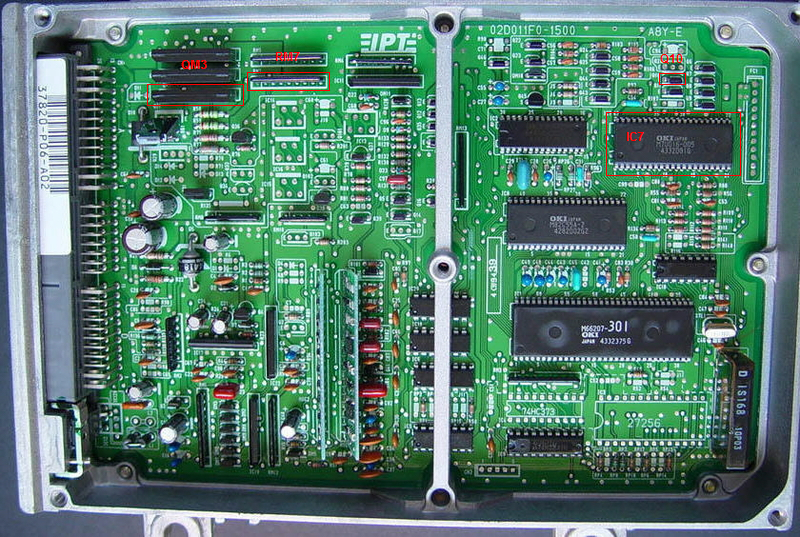
Theory of operation, and diagnosis:
1) The MCU tells IC7 to activate the fuel pump during first two seconds after the key is cycled, or anytime the engine is operating. It does this in a rather complex fashion, so if anything is wrong between the MCU and IC7 there are going to be a lot more problems than just the fuel pump not working. All you need to know is it communicates with IC7 about the fuel pump at these times.
2) IC7 sends a fuel pump activation signal by sending +5VDC out on pin 32. Seeing as how the ECU board has pin numbers silkscreened around the perimeter of IC7, if you can't figure out which pin you should go ahead and get a rope.
- No power on IC7 pin 32 indicates either a short to ground in the circuit, or a problem with IC7. Since the ECU board should be clean and free of obvious damage it is 99% likely the problem is with IC7.
* There should be power on IC7 pin 32
2) The +5VDC signal from IC7 activates transistor Q10 on pin 3, which tells it to transfer the +5VDC reference on pin 1 to pin 2. Q10's pins are not labeled, so you are going to have to count from left to right on the picture above, one... two... three. I didn't lose you, did I?
- No power on Q10 pin 1 indicates a bad +5VDC reference - which would affect other things than just fuel pump so it is NOT likely. The solder joint at Q10 pin 1 could be corroded or damaged with age.
- No power on Q10 pin 2 indicates a either a short on the board or, more likely, a bad Q10 transistor.
- No power on Q10 pin 3 indicates a bad connection with IC7 pin 32.
* There should be power on all three pins of Q10.
3) The +5VDC signal from Q10 pin 2 travels to RM7 pin7. RM7 is a funny looking package that holds a number of resistors. As far as the fuel pump circuit is concerned, RM7 keeps Q10 from drawing too much current and also keeps Q10 from passing too much current along to the main switching transistor in QM3, that controls the fuel pump curcuit directly. Oh noes, you have to count to nine.
- No power on RM7 pin 7 indicates a potential short to ground inside RM7. This is very unlikely, most resistors open when they go bad. More likely, a broken trace between Q10 pin 2 and RM7 pin 7.
- No power on RM7 pin 6 indicated a potential short to ground after RM7, or much more likely an open circuit between RM7 pin 7 and RM7 pin 6. (proceed to ECU unplugged tests below)
* ECU should have power in RM7 pin 7.
* ECU should have power on RM7 pin 6.
Test with the ECU unplugged and unpowered:
* RM7 pin 7 to RM7 pin 6 (current limiting resistor that prevents passing too much current to QM3) should have approximately 330 ohms resistance. An open circuit indicates a bad RM7.
* RM7 pin 7 to RM7 pin 1 (current limiting resistor that protects Q10) should have 1500-2500 ohms resistance. An open circuit indicates a bad RM7.
* RM7 pin 1 should have continuity with ground at ECU plug A23/A24
4) The +5VDC signal from RM7 pin 6 travels to, and activates, a higher powered switching transistor at QM3 pin 6. The transistor inside QM3, when powered on pin 6, makes a connection between QM3 pin 7 and QM3 pin 10. QM3 pin 7 is connected to ECU plug A7 (also A8, but unused) for grounding the fuel pump side of the main relay. QM3 pin 10 is connected to ground at A23/A24.
- No power on QM3 pin 6 indicates a bad connection with RM7 pin 6, or less likely a short to ground.
* ECU should have power on QM3 pin 6.
* ECU should ground a powered testlight at QM3 pin 7, or via ECU plug A7 or A8. If it does not, suspect either QM3 or it's ground at QM3 pin 10. (proceed to ECU unplugged tests below)
Test with the ECU unplugged and unpowered:
* ECU should have continuity between QM3 pin 10 and ECU plug A23/A24.
** All tests should be conducted with the ECU's fuel pump circuit active, unless otherwise stated. Either cycle key on and monitor circuit during the two second priming function, or manually power the pump itself and idle vehicle. **
Symptom: ECU does not provide ground signal to the main relay, which in turn causes the relay to send power to the fuel pump. ECU operates correctly in all other respects, and operates the vehicle when the fuel pump is powered manually.
Theory of operation, and diagnosis:
1) The MCU tells IC7 to activate the fuel pump during first two seconds after the key is cycled, or anytime the engine is operating. It does this in a rather complex fashion, so if anything is wrong between the MCU and IC7 there are going to be a lot more problems than just the fuel pump not working. All you need to know is it communicates with IC7 about the fuel pump at these times.
2) IC7 sends a fuel pump activation signal by sending +5VDC out on pin 32. Seeing as how the ECU board has pin numbers silkscreened around the perimeter of IC7, if you can't figure out which pin you should go ahead and get a rope.
- No power on IC7 pin 32 indicates either a short to ground in the circuit, or a problem with IC7. Since the ECU board should be clean and free of obvious damage it is 99% likely the problem is with IC7.
* There should be power on IC7 pin 32
2) The +5VDC signal from IC7 activates transistor Q10 on pin 3, which tells it to transfer the +5VDC reference on pin 1 to pin 2. Q10's pins are not labeled, so you are going to have to count from left to right on the picture above, one... two... three. I didn't lose you, did I?
- No power on Q10 pin 1 indicates a bad +5VDC reference - which would affect other things than just fuel pump so it is NOT likely. The solder joint at Q10 pin 1 could be corroded or damaged with age.
- No power on Q10 pin 2 indicates a either a short on the board or, more likely, a bad Q10 transistor.
- No power on Q10 pin 3 indicates a bad connection with IC7 pin 32.
* There should be power on all three pins of Q10.
3) The +5VDC signal from Q10 pin 2 travels to RM7 pin7. RM7 is a funny looking package that holds a number of resistors. As far as the fuel pump circuit is concerned, RM7 keeps Q10 from drawing too much current and also keeps Q10 from passing too much current along to the main switching transistor in QM3, that controls the fuel pump curcuit directly. Oh noes, you have to count to nine.
- No power on RM7 pin 7 indicates a potential short to ground inside RM7. This is very unlikely, most resistors open when they go bad. More likely, a broken trace between Q10 pin 2 and RM7 pin 7.
- No power on RM7 pin 6 indicated a potential short to ground after RM7, or much more likely an open circuit between RM7 pin 7 and RM7 pin 6. (proceed to ECU unplugged tests below)
* ECU should have power in RM7 pin 7.
* ECU should have power on RM7 pin 6.
Test with the ECU unplugged and unpowered:
* RM7 pin 7 to RM7 pin 6 (current limiting resistor that prevents passing too much current to QM3) should have approximately 330 ohms resistance. An open circuit indicates a bad RM7.
* RM7 pin 7 to RM7 pin 1 (current limiting resistor that protects Q10) should have 1500-2500 ohms resistance. An open circuit indicates a bad RM7.
* RM7 pin 1 should have continuity with ground at ECU plug A23/A24
4) The +5VDC signal from RM7 pin 6 travels to, and activates, a higher powered switching transistor at QM3 pin 6. The transistor inside QM3, when powered on pin 6, makes a connection between QM3 pin 7 and QM3 pin 10. QM3 pin 7 is connected to ECU plug A7 (also A8, but unused) for grounding the fuel pump side of the main relay. QM3 pin 10 is connected to ground at A23/A24.
- No power on QM3 pin 6 indicates a bad connection with RM7 pin 6, or less likely a short to ground.
* ECU should have power on QM3 pin 6.
* ECU should ground a powered testlight at QM3 pin 7, or via ECU plug A7 or A8. If it does not, suspect either QM3 or it's ground at QM3 pin 10. (proceed to ECU unplugged tests below)
Test with the ECU unplugged and unpowered:
* ECU should have continuity between QM3 pin 10 and ECU plug A23/A24.

Thread
Thread Starter
Forum
Replies
Last Post
AJxr
Turbo Parts For Sale
0
03-19-2007 09:47 PM
Walter
Wanted
9
03-05-2007 06:17 PM
Tom-Guy
Turbo Parts For Sale
8
06-11-2003 05:28 PM


